
Programming instructions


NC Programming 17VRS Tool Corrections
5-21
DOK-MTC200-NC**PRO*V17-ANW1-EN-P
The length corrections L1, L2, L3 of a tool edge are calculated as follows:
Len
g
th corretions L1 = len
g
th L1 + wear L1 + offset L1
Len
g
th corretions L2 = len
g
th L2 + wear L2 + offset L2
Len
g
th corretions L3 = len
g
th L3 + wear L3 + offset L3
Length L3: 210.000
+ Wear L3: -0.030
+ Offset L3: 0.015
= Length corr.L3: 209.985
L3_min=2000mm
Length correction L3=209.985mm
L3_max=230mm
Fig. 5-7: Length correction L3 using a drill bit as an example
The geometry data which apply to the tool with the selected correction
type are displayed on the PC and SOT user interfaces and are used in the
calculations in the controller
The radius correction
R
of a tool edge is calculated as follows:
Radius correction R = radius R + wear R + offset R
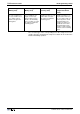
Determined correction values:
1) Not considering of radius
Correction type
Edge orientation
Lenth L3
Wear L3
1
0
162.13
Offset L3
0
0
1) Considering the radius
Correction type
Edge orientation
Lenth L3
Wear L3
2
0
162.13
Offset L3
0
0
Radius R
Wear R
8
Offset R
0
0
R
Length L3
Z
Fig. 5-8: Radius correction R using a roughing cutter as an example
Length corrections (L1, L2, L3)
Radius correction (R)