
Programming instructions


5-22
Tool Corrections NC Programming 17VRS
DOK-MTC200-NC**PRO*V17-ANW1-EN-P
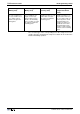
Examples For tool measurement
Determined correction values:
1) Not considering of radius
Correction type
Edge orientation
Lenth L3
Wear L3
1
0
162.13
Offset L3
0
0
1) Considering the radius
Correction type
Edge orientation
Lenth L3
Wear L3
2
0
162.13
Offset L3
0
0
Radius R
Wear R
8
Offset R
0
0
R
Length L3
Z
Abb. 5-9: Example: measuring a turning tool
Determined correction values:
Correction type
Edge orientation
Lenth L1
Wear L1
3
3
38.322
Offset L1
0
0
Length L2
Wear L2
Offset
197.827
0
0
Radius R
Wear R
3.2
Offset R
0
0
X
Z
L1
S
R
L2
Abb. 5-10: Example: measuring a drilling tool
Wear-induced tool length or tool radius changes can be compensated for
by means of wear factors.
Beginning with Version 4.14, the data fields for the wear factors are only
present in the tool list and are no longer displayed in the setup list.
Length wear compensation is activated when tool length correction is
activated via G48 or G49. The compensation value used to adjust for tool
length wear is calculated in the tool management system by multiplying
the duration of tool machining time by the length wear factor. If the length
wear factor is entered in mm/min or inch/min, the tool management sys-
tem uses the total time in which the tool was active while working motion
Wear factors
Length wear factors
(L1, L2 and L3)