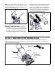
Operator’s Manual Chipper Shredder Vacuum Model Series 020 IMPORTANT: Read safety rules and instructions carefully before operating equipment Warning: This unit is equipped with an internal combustion engine and should not be used on or near any unimproved forest-covered, brush-covered or grass-covered land unless the engine’s exhaust system is equipped with a spark arrester meeting applicable local or state laws (if any).
TABLE OF CONTENTS Content Important Safe Operation Practices Assembling Your Yard Vacuum Know Your Yard Vacuum Operating Your Yard Vacuum Content Maintaining Your Yard Vacuum Troubleshooting Illustrated Parts List Warranty Page 3 5 6 7 Page 8 11 12 Back Cover FINDING MODEL NUMBER This Operator’s Manual is an important part of your new yard vacuum. It will help you assemble, prepare and maintain the unit for best performance. Please read and understand what it says.
SECTION 1: IMPORTANT SAFE OPERATION PRACTICES WARNING: This symbol points out important safety instructions which, if not followed, could endanger the personal safety and/or property of yourself and others. Read and follow all instructions in this manual before attempting to operate this machine. Failure to comply with these instructions may result in personal injury. When you see this symbol—HEED ITS WARNING.
Operation 12. Never operate this machine without good visibility or light. Always be sure of your footing and keep a firm hold on the handles. 13. Do not operate this machine on a gravel surface. 14. Do not operate this machine while under the influence of alcohol or drugs. 15. Muffler and engine become hot and can cause a burn. Do not touch. 16. Never pick up or carry machine while the engine is running. 1. Do not put hands and feet near rotating parts or in the feeding chambers and discharge opening.
SECTION 2: ASSEMBLING YOUR LAWN MOWER Removing Unit From Carton • • • • • Remove staples, break glue on top flaps, or cut tape at carton end and peel along top flap to open. Remove loose parts if included with unit (i.e., operator’s manual, grass bag, safety glasses etc.) Cut along corners, lay carton down flat, and remove packing material and bottle of oil, if any. Roll or slide unit out of carton and check carton thoroughly for loose parts.
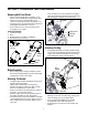
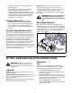
• NOTE: The safety switch button attached to the mounting bracket must be fully depressed by the front tab on the bag handle when securing the bag or the engine will not start. See Figure 4. • Front Tab Slip blower chute over rim of the discharge opening and release locking rod to secure chute in place. Make sure safety switch button is fully depressed by the front tab on the blower chute. See Figure 5. Raise the nozzle height to the highest setting when using the blower chute.
Bag Nozzle Height Adjustment Lever Collects shredded material fed through the chipper chute or vacuumed through the nozzle. Used to adjust ground clearance of the nozzle ranging approximately 5/8” to 4-1/8”. Bag Handle Nozzle Used to grasp bag in order to assist in attaching, removing and emptying bag. Yard waste such as leaves and pine needles can be vacuumed up through the nozzle for shredding.
• • • • • Remove bag from rim of the discharge opening. Refer to Figure 3. Twist the two buttons on the back of the bag to unlock and empty contents. See Figure 7. Hold bag handle and clip while emptying contents. Compress bag opening and fold inner flap over the opening. Fold outer flap over the inner flap and insert buttons on the bag through metal outlets. Twist buttons to lock the bag. IMPORTANT: The flail screen is located inside the housing in the discharge area.
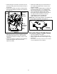
Removing The Flail Screen Sharpening Or Replacing Chipper Blade If the discharge area becomes clogged, remove the flail screen and clean area as follows: • • • • IMPORTANT: Because the engine on this unit has a tapered crankshaft, a special impeller tool (part number 753-0900) is required to remove the impeller assembly. For further assistance, contact your local service dealer. The instructions below involve use of this tool.
• • • Remove flange lock nut that secures flail screen to the lower housing. The flail screen does not have to be removed. Remove the hex bolt, lock washer, and flat washer that secure the impeller assembly to the crankshaft. See Figure 13. • • Upper Housing Chipper Blade • Impeller Assembly • Remove the blade using a 3/16” allen wrench on the outside of the blade and 1/2” wrench on the impeller assembly. Replace or sharpen chipper blade.
SECTION 6: TROUBLESHOOTING Problem Cause Remedy 1. Spark plug wire disconnected. 2. Fuel tank empty or stale fuel. 3. Throttle control lever (if so equipped) not in correct starting position. 4. Choke, if so equipped, not in CHOKE position. 5. Blocked fuel line. 6. Faulty spark plug. 7. Safety switch not depressed. 1. Connect wire to spark plug. 2. Fill tank with clean, fresh gasoline. 3. Move throttle lever to FAST position. 1. Spark plug wire loose. 2. Unit running on CHOKE. 4.
SECTION 7: PARTS LIST FOR MODEL SERIES 020 1 29 2 29 2 4 6 3 8 7 5 10 12 13 11 19 9 16 14 11 22 15 23 25 18 16 20 17 21 27 24 26 28 12
Model Series 020 Ref. No. 1. 2. 3. 4. 5. 6. 7. 8. 9. 10. 11. 12. 13. 14. 15. 16. 17. 18. 19. 20. 21. 22. 23. 24. 25. 26. 27. 28. 29. Part No.
Model Series 020 1 2 3 5 4 11 6 12 11 8 10 9 14 11 18 19 17 18 15 11 16 20 18 16 21 22 36 23 24 26 29 27 28 30 31 32 33 35 13 13 34 7 14
Model Series 020 Ref. No. Part No. 1. 2. 3. 4. 5. 6. 7. 8. 9. 10. 11. 12. 13. 14. 15. 16. 17. 18. 19. 20. 21. 22. 23. 24. 26. 27. 28. 29. 30. 31. 32. 33. 34. 35. 36.
MANUFACTURER’S LIMITED WARRANTY FOR: The limited warranty set forth below is given by MTD LLC with respect to new merchandise purchased and used in the United States, its possessions and territories. “MTD”warrants this product against defects in material and workmanship for a period of two (2) years commencing on the date of original purchase and will, at its option, repair or replace, free of charge, any part found to be defective in materials or workmanship.