® Operator’s Manual MODEL 214 IP 216 IP 214 KW 216 KW IMPORTANT: READ SAFETY RULES AND INSTRUCTIONS CAREFULLY Warning: This unit is equipped with an internal combustion engine and should not be used on or near any unimproved forestcovered, brush-covered or grass-covered land unless the engine’s exhaust system is equipped with a spark arrester meeting applicable local or state laws (if any). If a spark arrester is used, it should be maintained in effective working order by the operator.
SECTION 1: IMPORTANT SAFE OPERATION PRACTICES WARNING: THIS SYMBOL POINTS OUT IMPORTANT SAFETY INSTRUCTIONS WHICH, IF NOT FOLLOWED, COULD ENDANGER THE PERSONAL SAFETY AND/OR PROPERTY OF YOURSELF AND OTHERS. READ AND FOLLOW ALL INSTRUCTIONS IN THIS MANUAL BEFORE ATTEMPTING TO OPERATE YOUR LAWN MOWER. FAILURE TO COMPLY WITH THESE INSTRUCTIONS MAY RESULT IN PERSONAL INJURY. WHEN YOU SEE THIS SYMBOL, HEED ITS WARNING.
• Do not engage the self-propelled mechanism on units so equipped while starting engine. • Always be sure of your footing. A slip and fall can cause serious personal injury. If you feel you are losing your balance release the blade control handle immediately and the blade will stop in less than 3 seconds. • The blade control handle is a safety device. Never attempt to bypass its operation.
• Never run an engine inside a closed area. Exhaust gases contain carbon monoxide. This odorless gas can be deadly when inhaled. • Keep all nuts, bolts, and screws tight to be sure the equipment is in safe working condition. • Never tamper with safety devices. Check their proper operation regularly. • When filling the fuel tank, stop when the gasoline reaches one inch from the top. This space must be left for expansion. Do not overfill.
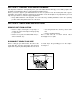
USE THIS PAGE AS A GUIDE TO DETERMINE SLOPES WHERE YOU MAY NOT OPERATE SAFELY. SIGHT AND HOLD THIS LEVEL WITH A VERTICAL TREE A POWER POLE A CORNER OF A BUILDING OR A FENCE POST ON D O TTE D LINE , RE PRE SEN TIN GA 15° S LOP E 5 SLOPE GAUGE FOL D 15° WARNING Do not mow on inclines with a slope in excess of 15 degrees (a rise of approximately 2-1/2 feet every 10 feet). A riding mower could overturn and cause serious injury.
SECTION 1: FINDING YOUR MODEL NUMBER This Operator’s Manual is an important part of your new walk behind. It will help you assemble, prepare and maintain your walk behind. Please read and understand what it says. Before you start to prepare your walk behind for its first use, please locate the model plate and copy the information from it in this Operator’s Manual. The information on the model plate is very important if you need help from your dealer or customer support department.
SECTION 3: SET-UP INSTRUCTIONS ITEMS REQUIRED FOR ASSEMBLY • 7/16" and 1/2" wrench or socket • Motor Oil (SAE 10W30) • Fresh Gasoline IMPORTANT: This unit is shipped WITHOUT GASOLINE or OIL (unless carton is marked as “audit machine”) in the engine. Be certain to service engine with gasoline and oil as instructed in the separate engine manual before operating your mower. NOTE: Reference to right or left hand side of the mower is observed from the operating position.
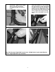
Step 3. Replace the hardware removed from the Step 4. lower handle. Tighten all four handle (two on each side of the handle assembly) nuts with 1/2" wrench or socket. Remove Raise the complete handle assembly until it lines up with one of the mounting holes in the struts. Put the carriage bolt through the struts and then through the handle. Place the saddle washer on the bolt and then fasten with the wing nut by hand.
Step 5. Attach control cables to handle with pull ties found on the handle. HERE Step 6. Loosen the nut holding the rope guide to the upper handle with a 7/16" wrench or socket. Step 7. Squeeze the blade control bail against the upper handle and pull out starter rope, slowly! . (Models without BBC) Step 8. Thread starter rope into rope guide. Step 9. Tighten nut.
SECTION 4: CONTROLS Blade Control Bail Drive Clutch Control Bail Blade Brake Control Throttle Control Recoil Starter BLADE BRAKE CONTROL MODEL ENGINE BRAKE CONTROL MODEL Figure 2 BLADE CONTROL BAIL For units equipped with Engine Brake Control: The blade control bail is located on the handle of the mower. See Figure 2. The blade control bail must be depressed in order to start and operate the unit. Release the blade control bail to stop the engine and blade.
WARNING: Shift lever only with the engine running. Shifting with the Drive Clutch Control engaged can damage the transmission. CUTTING HEIGHT ADJUSTMENT LEVERS The cutting height adjustment levers are located above each wheel. Cutting heights are from 3/4” to 4-1/2" with 3/8" increments. The low range setting is 3/4" to 2-5/8” and the high range setting is from 2-5/8” to 4-1/2”. To adjust the cutting height, push the levers away from the mower and then move it forward or back for a new cutting height.
EACH TIME BEFORE YOU START YOUR MOWER • Attach spark plug wire to spark plug. Make certain the metal cap on the end of the spark plug wire is fastened securely over the metal tip on the spark plug. TO START ENGINE AND ENGAGE BLADE • Move the throttle control lever all the way forward. (This will activate choke on some models). • Prime engine as instructed in the separate engine manual. (If required). • For engine brake models only.
BAGGING GRASS CLIPPINGS This mower can bag grass clippings. Follow steps 1 and 2 to ready the mower for bagging. Step 1. Remove mulching plug, if installed. Step 2. Hang grass bag on mower. HERE LIFT PULL EMPTYING A FULL BAG OF GRASS Once the grass bag is full it will need to be emptied, follow steps 3 and 4 to empty the grass bag. Step 3. Lift flap and pull bag away from mower. Step 4. Lift bag up and away from mower. Dump the grass clippings.
SIDE DISCHARGING GRASS CLIPPINGS (Optional) Step 1. Side Discharge Top and Left View. This side up Lift rear flap, remove grass bag, or mulch plug if installed,. Hang side discharge chute. LIFT Hang SECTION 6: ADJUSTMENTS WARNING: Do not at any time make any adjustment to lawn mower without first stopping engine and disconnecting spark plug wire. HANDLE HEIGHT ADJUSTMENT • See the ASSEMBLY SECTION for handle height adjustment.
SECTION 7: LUBRICATION WARNING: Always stop engine and disconnect spark plug wire before cleaning, lubricating or doing any kind of work on the lawn mower. Blade Control Handle LUBRICATE Wheels Axle Shafts Engine SEE ENGINE MANUAL Figure 4 Blade Control: Lubricate the pivot points on the blade control handle and the brake cable at least once a season with light oil. See Figure 4. The blade control must operate freely in both directions.
DECK The underside of the mower deck should be cleaned after each use to prevent a buildup of grass clippings, leaves, dirt or other matter. If this debris is allowed to accumulate, it will invite rust and corrosion, and may prevent proper mulching, discharge or bagging. The deck may be cleaned by tilting the mower and scraping clean with a suitable tool (make certain the spark plug wire is disconnected).
SECTION 9: OFF-SEASON STORAGE The following steps should be taken to prepare lawn mower for storage. • Clean and lubricate mower thoroughly as described in the lubrication instructions. • Refer to engine manual for correct engine storage instructions. • Coat mower’s cutting blade with chassis grease to prevent rusting. • Store mower in a dry, clean area. Do not store next to corrosive materials, such as fertilizer.
EQUIPMENT TWO-YEAR LIMITED WARRANTY This warranty is specific to the product manual it is attached to. For a complete list of products and warranties contact your MTD Pro dealer. Proper maintenance of your MTD Pro equipment is the owner’s responsibility. Follow the instructions in your owner’s manual for correct lubricants and maintenance schedule. Your MTD Pro dealer carries a complete line of quality lubricants and filters for your equipment’s engine, transmission, chassis and attachments. 1.