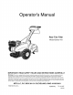
Operator's Manual Rear Tine Tiller Model Series 410 IMPORTANT: READ SAFETY RULES AND INSTRUCTIONS CAREFULLY Warning: This unit is equipped with an internal combustion engine and should not be used on or near any unimproved forestcovered, brush-covered or grass-covered land unless the engine's exhaust system is equipped with a spark arrester meeting applicable local or state laws (if any), If a spark arrester is used, it should be maintained in effective working order by the operator, In the State of
This Operator's Manual is an important part of your new tiller. It will help you assemble, prepare and maintain the unit for best performance. Please read and understand what it says.
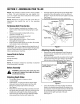
SECTION1: IMPORTANT SAFEOPERATION PRACTICES WARNING: This symbol points out important safety instructions which, if not followed, could endanger the personal safety and/or property of yourself and others. Read and follow all instructions in this manual before attempting to operate this machine. Failure to comply with these instructions may result in personal injury. When you see this symbol - heed its warning.
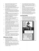
7. 8. 9. 10. 11. Neveroperate themachine athightransport Do not change the engine governor settings or speedsonhardorslippery surfaces. over-speed the engine. The governor controls the Exercise cautiontoavoidslipping orfalling. maximum safe operating speed of the engine. Lookdownandbehindandusecarewhenin Maintain or replace safety and instruction labels, as reverse orpullingmachine towards you. necessary. Starttheengineaccording totheinstructions found 6.
SECTION2: ASSEMBLING YOURTILLER NOTE: This operator's manual covers various models of tillers. The units illustrated may vary slightly from your unit. Follow only those instructions which pertain to your model number. Insert hex bolt into the top hole of the depth stake assembly. Place flat washer on the hex bolt and thread "T" knob onto the hex bolt. Tighten securely. See Figure 1. Tip the tiller back down so it rests on the tines.
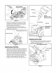
Retainer Bracket Shoulder Bolt & Lock Nut Handle ustment Rod (Model Series 420) Gear Figure 3 • • Gear Shift Rod Place the hex opening of the flange nut retainer bracket over the flange nut securing the handle adjustment crank and install the lock nut on the lower shoulder bolt. See Figure 4. Pivot handle assembly into position desired. Tighten the bottom bolt, lock nut, and the handle adjustment lock securely.
• • Remove one hex nut from the threaded casing on the end of the cable. Slip the wire up through the slot on the cable bracket underneath the handle. Push the end of the casing up through the cable bracket. Rethread the hex nut on the end of the cable. Do not tighten at this time. Hex Nut \ Lock Washer Rex End Slot in Cable Bracket (Viewed From Under Handle) Figure 7 Pull the cable upwards to obtain slack and hook the Z end of the cable from right to left into the bracket on the clutch control (bene
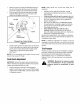
SECTION3: KNOWYOURTILLER Handle Handle Handle Adjustment_ Handle Stake Model 410 Series Figure 8 all instructions warningsandonfollow the WARNING: Read, and understand, machine and in this manual before operating. GearSelectionHandle The gear selection handle is located on the front of the handle assembly. It is used to select NEUTRAL, REVERSE, or one of the FORWARD modes. This tiller is designed for the gear selection handle to be moved while the engine is running.
ChokeLever(if Equipped) FuelShut-OffValve(_fEquipped) The choke lever is located on top of the carburetor on the back of the engine underneath the muffler. It is used to enrich the fuel mixture in the carburetor when starting a cold engine. Make sure the valve is in the On (horizontal) position when starting the unit. Any time the tiller is not in operation (i.e., storing, performing maintenance or adjustment), make sure the valve is in the OFF (vertical) position.
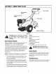
SECTION4: OPERATING YOURTILLER • ,_ all instructions warningsandon the WARNING: Read, and understand, follow machine and in this manual before operating. • BeforeStarting • • GasAndOil Fill-Up Service the engine with gasoline and oil as instructed in the separate engine manual packed with your tiller. Read instructions carefully.
• When using the tiller for the first time, use the second adjustment hole from the top (1" of tilling depth). See Figure 9. Use This Position _ First To adjust the depth stake, remove the clevis pin and hairpin clip. Move the depth stake to the desired setting and secure with the clevis pin and hairpin clip. See Figure 9. To adjust the side shields, remove the wing nuts. Move the side shield to the desired position and replace the wing nuts. Tighten securely.
SECTION5: MAKINGADJUSTMENTS _, BeltTensionAdjustment adjustments while the engine running, WARNING: Never attempt to is make any except where specified in operator's manual. Periodic adjustment of the belt tension may be required due to normal stretch and wear on the belt. Adjustment is needed if the tines or wheels seem to hesitate while turning, but the engine maintains the same speed. HandleAdjustment To adjust the tension on the belt, refer to Final Clutch Adjustment in Assembly Instructions.
SECTION6: MAINTAININGYOURTILLER _, Remove tine assemblies and lubricate the tine shafts at least once a season. and ground it against the engine before WARNING: Disconnect the spark plug wire performing any repairs or maintenance. Wheel Shafts Remove wheel assemblies and lubricate the axle shafts at least once a season. Engine Refer to the separate engine manual for engine maintenance instructions. Cleaning TineArea Maintain engine oil as instructed in the separate engine manual packed with your unit.
NOTE: Upon Off-Season Storage reassembly, make certain the belt is routed over the idler pulley and inside of belt keepers by engine pulley. See Figure 10. I Engine Pulley If the tiller will not be used for a period longer than 30 days, the following steps should be taken to prepare the tiller for storage. Belt Keeper Hex Bolt • Clean the exterior of engine and the entire tiller thoroughly. Lubricate the tiller as described in the lubrication instructions.
SECTION7: TROUBLE SHOOTING GUIDE Trouble Possible Engine fails to start Fuel tank empty, or stale fuel. Fill tank with clean, fresh gasoline. Fuel will not last over thirty days unless a fuel stabilizer is used. Throttle control lever not in correct starting position (if so equipped). Blocked fuel line. Move throttle lever to start position. Dirty aircleaner. Refer to the engine manual packed with your unit. Choke not in ON position. Move choke to ON position. Spark plug wire disconnected.
SECTION8: PARTSLISTFORMODELSERIES410 1 5 8 29 23 \ 1 \ 32 I 28 25 26 3, 35 39 I I I i 41 4O I I 16 18 16 19
ModelSeries410 Ref. No. Part No. Ref. No. Part Description Part No. Part Description 1. 710-1017 Hex Screw 1/4-20 x.625 22. 686-0031A 2. 786-0168 Shift Cover - Tecumseh 23. 736-0119 Belt Keeper Bracket Ass'y Lock Washer 5/16 3. 686-0095 24. 710-0237 Hex Cap Screw 5/16-24 x.625 4. 5. 712-04063 715-0120 Crank Shift Assembly Hex Lock Nut 5/16-18 Spiral Pin 25. 26. 756-0971 756-0972 6. 786-0117 Shift Cover Mounting Bracket 27. 754-0438 Outer Pulley Half V-Belt 7.
ModelSeries410 32 36 38 9 24 25 25 13 \ \ 23 3 2 18
ModelSeries410 Ref. No. Part No. Ref. No. Part Description 721-0378 Shaft Seal 1.0 Dia 2. 712-0378 Hex Nut 7/16-20 3. 736-0407 Bell Washer.45 ID x 1.00D 4. 721-0379 5. Part No. Part Description 786-0086 Reinforcement 30. 721-0295 Chain Case Gasket 31. 710-0258 Shaft Seal.75 Dia 32. 736-0329 Hex Cap Screw 1/4-20 x.625 Lock Washer 1/4 716-0865 Snap Ring.50 Dia 33. 736-0512 Flat Washer.281 ID x.875 OD 6. 7. 686-0038 618-0245B Gear Case Assembly - RH Half 34.
ModelSeries410 / 3 1o_ -7 23 25 10 _/ J J j v J J J J 17 J J _1 J J J J J J 32 \ 17 42_ 43 20 26 /
ModelSeries410 Ref. No. Part No. 1. 710-1017 2. 786-0131 3. Ref. No. Part Description Part No. Part Description Tap Screw 1/4-14 x.625 Handle Cover w/o Throttle 25. 26. 726-0106 747-0432 Cap Nut Rod 710-0896 720-0278A Hex Washer Screw 1/4-14 x.625 27. 786-0113 Rear Tine Shield Flap Foam Grip 28. 710-3005 735-0246 End Plug 29. 736-0117 Hex Cap Screw 3/8-16 x 1.25 Flat Washer.375 ID x.620 OD 6. 647-0014 7. 786-0118 Clutch Control Assembly Return Bracket - LH 30. 31.
NOTES 22
NOTES 23
MANUFACTURER'S LIMITED WARRANTY The limited warranty set forth below is given by MTD LLC with respect to new merchandise purchased and used in the United States, its possessions and territories. "MTD"warrants this product against defects in material and workmanship for a period of two (2) years commencing on the date of original purchase and will, at its option, repair or replace, free of charge, any part found to be defective in materials or workmanship.