Operator’s Manual 20” Rotary Lawn Mower Models 020 021 022 IMPORTANT: Read safety rules and instructions carefully before operating equipment. Warning: This unit is equipped with an internal combustion engine and should not be used on or near any unimproved forestcovered, brush-covered or grass-covered land unless the engine’s exhaust system is equipped with a spark arrester meeting applicable local or state laws (if any).
TABLE OF CONTENTS Content Page Important Safe Operation Practices................................................................... 3 Slope Gauge...................................................................................................... 6 Hardware Pack .................................................................................................. 7 Assembling Your Lawn Mower........................................................................... 7 Know Your Lawn Mower ...................
SECTION 1: IMPORTANT SAFE OPERATION PRACTICES WARNING: This symbol points out important safety instructions which, if not followed, could endanger the personal safety and/or property of yourself and others. Read and follow all instructions in this manual before attempting to operate this machine. Failure to comply with these instructions may result in personal injury. When you see this symbol—HEED ITS WARNING.
5. discharge cover, grass catcher, blade control handle or other safety protective devices in place and working. Never operate mower with damaged safety devices. Failure to do so, can result in personal injury. 14. Muffler and engine become hot and can cause a burn. Do not touch. 15. Only use parts and accessories made for this machine by the manufacturer. Failure to do so, can result in personal injury. 16. If situations occur which are not covered in this manual, use care and good judgment.
3. 4. 5. 6. 7. 8. adjustment while the engine is running. Grass catcher components, discharge cover, and trail shield are subject to wear and damage which could expose moving parts or allow objects to be thrown. For safety protection, frequently check components and replace immediately with original equipment manufacturer’s (O.E.M.) parts only, listed in this manual. “Use of parts which do not meet the original equipment specifications may lead to improper performance and compromise safety!” 10.
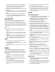
ON D WARNING R INE, N E SE EPR 15° TING ° SL A 15 O PE Do not mow on inclines with a slope in excess of 15 degrees (a rise of approximately 2-1/2 feet every 10 feet). A riding mower could overturn and cause serious injury. If operating a walk-behind mower on such a slope, it is extremely difficult to maintain your footing and you could slip, resulting in serious injury. Operate RIDING mowers up and down slopes, never across the face of slopes.
SECTION 3: HARDWARE PACK Group 2 Group 4 Group 5 Group 1 Group 6 Group 3 SECTION 4: ASSEMBLING YOUR LAWN MOWER NOTE: This operator’s manual covers various models of mowers. Follow only those instructions which pertain to your unit. Bolt Tools Required Spark Plug Wire A set of adjustable wrenches or individual wrenches of the following sizes:7/16”, 1/2”, 9/16”, 3/4”. NOTE: Reference to right or left hand side of the mower is observed from the operating position.
• • • Install the hex screws, shoulder screws and flange nuts from group 4 of the hardware pack. Using two 1/2” wrenches, tighten securely. See Figure 2. Lower Handle Route the cable under the lower handle. On the opposite end of the cable housing is a snap fitting. The shaft inside the snap fitting fits in the second hole on the upper handle. Press the snap fitting in place as shown in Figure 4. Make sure that the blade control handle is on top of the upper handle.
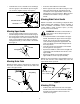
• • • • • • Z Fitting Attaching Chute Deflector Figure 6 • Securing Brake Cable • WARNING: The cable must be routed properly to avoid contact with all sharp edges and hot surfaces. Such contacts damage the cable and render the controls inoperative. • Block the mower securely. Using hardware from group 1 of the hardware pack, place axle bolt through the wheel with the hub side of the wheel facing the deck. See Figure 8.
Know Your Lawn Mower Compare the illustration in Figure 11 Figure 11with your lawn mower to familiarize yourself with the location of various controls and adjustments. Blade Control Handle Throttle Control Recoil Starter The mower engine is equipped with a constant speed throttle, which is set at full throttle for best performance. Engine Blade Control Handle The blade control handle is located on the upper handle of the mower.The blade control handle must be depressed in order to operate the unit.
Using Your Lawn Mower • • WARNING: Never operate your unit without either the rear deflector or entire grass catcher assembly in place. • • For a healthy lawn, never cut more than one-third of the total length of the grass at any one cutting. This mower is designed to operate at full throttle. WARNING: If you strike a foreign object, stop the engine. Remove wire from spark plug, thoroughly inspect the mower for any damage, and repair the damage before restarting and operating the mower.
Wheels To balance blade • • The wheels require no lubrication. However, if the wheels are removed for any reason, lubricate the surface of the axle bolt and the inner surface of the wheel with light oil. Engine oil may also be used. When sharpening the blade, follow original angle of grind as a guide. It is extremely important to grind off all edges equally to keep the blade balanced.
SECTION 8: OFF-SEASON STORAGE The following steps should be taken to prepare lawn mower for storage. • • NOTE: When storing any type of power equipment in an unventilated or metal storage shed, care should be taken to rust-proof the equipment. Using a light oil or silicone, coat the equipment, especially cables and all moving parts. • • Clean and lubricate mower thoroughly as described in the lubrication instructions. Refer to engine manual for correct engine storage instructions.
SECTION 10: PARTS LIST FOR MODEL SERIES 020 5 4 27 26 15 18 19 21 19 3 20 29 16 22 17 23 7 24 29 28 16 24 6 25 28 1 22 23 24 22 23 15 14 25 2 28 10 28 12 24 23 11 13 22 9 8 14 30
Model Series 020 Ref. No. 1. 2. 3. 4. 5. 6. 7. 8. 9. 10. 11. 12. 13. 14. 15. 16. 17. 18. 19. 20. 21. 22. 23. 24. 25. 26. 27. 28. 29. 30. Part No. Description 710-0654A Hex Ind. Washer Screw 3/8-16 x 1.0 782-0048 Cutting Deck: 20” 749-04037 Lower Handle 749-1092A Upper Handle 747-1161A Control Handle (Bail) 731-0872A Rear Flap 17098 Hinge Clip 710-1044 Screw 3/8-24 x 1.
MANUFACTURER’S LIMITED WARRANTY FOR: The limited warranty set forth below is given by MTD LLC with respect to new merchandise purchased and used in the United States, its possessions and territories. MTD LLC warrants this product against defects for a period of one (1) year commencing on the date of original purchase and will, at its option, repair or replace, free of charge, any part found to be defective in materials or workmanship.