Safety • Assembly • Operation • Tips & Techniques • Maintenance • Troubleshooting • Parts Lists • Warranty OPERATOR’S MANUAL Single-Stage Snow Thrower Model 235, S235 IMPORTANT READ SAFETY RULES AND INSTRUCTIONS CAREFULLY BEFORE OPERATION Warning: This unit is equipped with an internal combustion engine and should not be used on or near any unimproved forest-covered, brushcovered or grass-covered land unless the engine’s exhaust system is equipped with a spark arrester meeting applicable local or state
This Operator’s Manual is an important part of your new snow thrower. It will help you assemble, prepare and maintain the unit for best performance. Please read and understand what it says. Table of Contents Safety Labels .............................................. p. 3 Safe Operation Practices ........................... p. 4 Setting Up Your Snow Thrower .................. p. 6 Know Your Snow Thrower .......................... p. 7 Operating Your Snow Thrower ................... p.
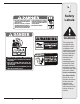
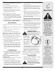
1 �� ������������������������������ �� ���������������������������������� �������������������������������� ������������������������������������� ��������������� ������������������������������������ ���������������� �� ������������������������������������� Safety Labels ������������������������������������ �� ����������������������� �������������������������������� �������������������������������� ������ WARNING ������ �������������������������������������� ������������������������������������ ���������
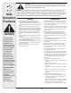
2 Safe Operation Practices WARNING This symbol points out important safety instructions which, if not followed, could endanger the personal safety and/or property of yourself and others. Read and follow all instructions in this manual before attempting to operate this machine. Failure to comply with these instructions may result in personal injury. When you see this symbol.
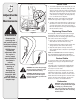
Operation Maintenance & Storage 1. Do not put hands or feet near rotating parts, in the auger/impeller housing or chute assembly. Contact with the rotating parts can amputate hands and feet. 2. The auger/impeller control lever is a safety device. Never bypass its operation. Doing so makes the machine unsafe and may cause personal injury. 3. The control levers must operate easily in both directions and automatically return to the disengaged position when released. 4.
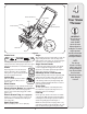
3 NOTE: This Operator’s Manual covers several models. Snow thrower features vary by model. Not all features discussed in this manual are applicable to all snow thrower models. 1 NOTE: All references to left or right side of the snow thrower is from the operating position only Setup And Adjustment Contents of Carton Carton contents are listed below with part numbers in parentheses. 1. Two Ignition Keys (725-0201) 2 2. 2.6 oz Bottle of 2 Cycle Oil (737-04037) 3.
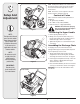
4 Auger Control Handle Electric Starter Button Starter Handle Key Fuel Cap Primer Chute Assembly Spark Plug Access Choke Lever Shave Plate Auger Figure 4 Auger Choke Lever OFF CHOKE ON When engaged, the augers rotation draws snow into the auger housing and throws it out the discharge chute. Rubber paddles on the augers also aid in propelling the unit as they come in contact with the pavement. Activating choke control closes the choke plate on carburetor and aids in starting engine.
5 Electric Starter Button (if equipped) Operation Starter Handle Figure 5A Primer Key Spark Plug Access Fuel Cap Chute Assembly WARNING Read, understand, and follow all instructions and warnings on the machine and in this manual before operating. Use extreme care when handling gasoline. Gasoline is extremely flammable and the vapors are explosive. Never fuel the machine indoors or while the engine is hot or running. Extinguish cigarettes, cigars, pipes and other sources of ignition.
5. If you have a grounded three-prong receptacle, proceed as follows. 6. Move Choke Control to the “Full” position. 7. Push Primer three (3) times, making sure to cover vent hole when pushing. 8. Connect power cord to switch box on dash panel. Plug the other end of power cord into a three-prong 120-volt, grounded, AC receptacle. 9. Push starter button to crank engine. 10. When engine starts, release starter button, and move choke gradually to 1/2 Choke until the engine runs smoothly. Next move Choke to OFF.
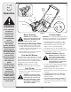
6 Shave Plate Side View Adjustments & Maintenance NOTE: On new units or units with a new shave plate installed, the augers may be slightly off the ground. 2. To adjust, tip the snow thrower back so that it rests on the handle. Loosen the four lock nuts and bolts which secure the shave plate to the housing. See Figure 7. Move the shave plate to desired position and retighten the nuts and bolts securely.
1. Refer to the separate engine manual, packed with your unit, for carburetor adjustment information Replacing Belt WARNING: Before servicing, repairing, or inspecting, disengage the control bail and stop engine. Wait until all moving parts have come to a complete stop. Disconnect spark plug wire and ground it against the engine to prevent unintended starting. Idler Pulley Remove the belt cover by removing five hex screws. See Figure 9.
7 Off-Season Storage WARNING Never store snow thrower with fuel in tank indoors or in poorly ventilated areas, where fuel fumes may reach an open flame, spark or pilot light as on a furnace, water heater, clothes dryer or gas appliance. Drain fuel into an approved container outdoors, away from any open flame. Be certain engine is cool. Do not smoke. Fuel left in engine during warm weather deteriorates and will cause serious starting problems. Do not drain carburetor if using fuel stabilizer.
Problem Engine fails to start Possible Cause(s) Solution 1. 2. 3. 4. 5. 6. Fuel tank empty, or stale fuel Improper fuel mixture Blocked fuel line Key not in ON position Spark plug wire disconnected Faulty spark plug 7. Engine not primed 8. Engine flooded from excessive priming Engine runs erratic Engine overheats Loss of power Excessive vibration Unit fails to self-propel 1. Unit running on choke 2. Fuel line blocked, or stale fuel Fill tank with clean fresh gasoline.
7 50 49 54 53 14 11 51 You can determine which drive pulley system your unit has by measuring this hole. Units with a 3/8” hole use these part numbers. 3 13 45 8 46 6 23 52 1 15 7 12 33 You can determine which drive pulley system your unit has by measuring this hole. Units with a 1/4” hole use these part numbers.
9 Part List: REF NO. PART No. DESCRIPTION Qty. REF NO. PART No. DESCRIPTION 1 629-0236 Extension Cord 1 28 712-04064 Hex Flange Lock Nut, 1/4-20 1 2 710-0627 Hex Screw, 5/16-24 x .75 1 29 726-0299 Push Cap, 1/2” 2 6 710-1003 Screw, #10-16 x .625 2 30 732-0357A Extension Spring 1 4 710-3025 Hex Screw, 5/16-18 x .625 4 31 736-0176 Flat Washer .265 x .938 x .120 4 5 712-04063 Hex Flange Lock Nut, 5/16-18 2 32 736-0326 Flat Washer .510 x 1.0 x .
9 32 19 38 Part List: 33 Snow Thrower 22 17 15 21 20 6 4 For parts and/or accessories please call 1-800-949-4483 8 5 7 www.whiteoutdoor.
REF NO. PART NUMBER DESCRIPTION Qty. 1 684-04127 Chute Assembly 1 2 710-04071 Carriage Bolt 5/16-18 x 1.0” 1 3 710-0451 Carriage Bolt 5/16-18 x 0.750” 1 4 712-04063 Flange Lock Nut, 5/16-18 6 5 720-0284 Chute Knob Assembly 1 6 731-04388A Chute Handle 1 7 731-04426A Upper Chute 1 8 736-0159 Washer 1 9 710-0487 Carriage Bolt 5/16-18 x 2.0 Gr. 1 2 10 720-0284 Handle Knob Assembly 5/16-18 2 11 725-0157 Cable Tie 1 12 736-0451 Saddle Washer .320 x .
10 Accessories & Kits The following accessories and kits are available for single-stage, two-cycle snow throwers. See the retailer from which you purchased your snow thrower, an authorized MTD Service Dealer or phone (800) 800-7310 for information regarding price and availability MODEL DESCRIPTION OEM-390-697 Electric Start Kit (fits models with a two-cycle Tecumseh 3 HP or 3.5 HP engine) OEM-390-996 Electric Start Kit (fits models with a two-cycle Tecumseh 4.5 HP – 5.
11 NOTES: Use this page to make notes and write down important information. For parts and/or accessories please call 1-800-949-4483 www.whiteoutdoor.
MANUFACTURER’S LIMITED WARRANTY FOR The limited warranty set forth below is given by MTD LLC with respect to new merchandise purchased and used in the United States, its possessions and territories. “MTD” warrants this product against defects in material and workmanship for a period of two (2) years commencing on the date of original purchase and will, at its option, repair or replace, free of charge, any part found to be defective in materials or workmanship.