Operator's Manual I:RRFrSMRN° 21" SNOW THROWER Model No. 247.887821 CAUTION: Before using this product, read this manual and follow all safety rules and operating instructions. Sears Brands Management Corporation, Visit our website: Hoffman • SAFETY • ASSEMBLY • OPERATION • MAINTENANCE • PARTS LIST • ESPANOL Estates, IL 60179, U.S.A. www.craftsman.com FormNo.
Warranty Statement ................................... 2 Parts List ............................................. 24 Safety Instructions 3 Engine Parts List ..................................... 28 7 Labels ............................................... 36 11 Repair Protection 37 14 Espa_ol .............................................. Off-Season Storage ................................... 19 Service Numbers ............................ Troubleshooting 20 .............................
Thissymbolpointsout importantsafety instructionswhich, if not followed, couldendangerthe personalsafetyand/or property of yourself and others.Readandfollow all instructions in this manual beforeattempting to operatethis machine.Failureto complywith these instructions may resultin personalinjury.
OPERATION CLEARING A CLOGGED DISCHARGE CHUTE Donot put handsor feetnearrotatingparts,inthe auger/impellerhousing or chuteassembly. Contactwith the rotatingpartscanamputatehandsand feet. Handcontactwith the rotatingimpellerinsidethe dischargechuteisthe most commoncauseof injuryassociated with snowthrowers.Neveruseyourhandto cleanout the dischargechute. Theauger/impellercontrolleverisasafetydevice.Neverbypassitsoperation. Doingsomakesthe machineunsafeandmaycausepersonalinjury. Toclearthe chute: a.
DO NOT MODIFY ENGINE Toavoidseriousinjuryor death,donot modify engineinanyway.Tampering with the governorsettingcanleadto arunawayengineandcauseit to operate at unsafespeeds.Nevertamperwith factorysetting of enginegovernor.
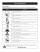
SAFETY SYMBOLS Thispage depicts and describes safety symbols that may appear on this product. Read, understand, and follow all instructions on the machine before attempting to assemble and operate. READ THE OPERATOR'S MANUAL(S) Read, understand, and follow all instructions in the manual(s) before attempting to assemble and operate WARNING-- ROTATING BLADES Keep hands out of inlet and discharge openings inside WARNING-- machine is running.
NOTE" Allreferencesto the [eft or right sideof thesnowthrowerarefrom the operator'sposition.Anyexceptions wi[[ be noted. Pivotthe upperhandleintothe operatingposition.Besurenot to pinchany of the cablesinthe process. SeeFigure2. Unpacking the SnowThrower 1. Openthe top ofthe carton. 2. Cutdownthe cornerson thefront of the cartonandfold downthe front side. 3. Pullthe snowthrowerout of the carton.Besurenot to damagethe chute, chuterotationcontrolassemblyor anycablesattachedto the chute.
Installing the Chute Installing the Chute Rotation Control Assembly 1. 1. Removethe hexwasherscrewsinthe chutebase.SeeFigure4. f Removethe fourhexwasherscrewsfrom the backofthe handle(two on eachside).SeeFigure6. Hex Screw / / Figure4 2. Figure6 Alignthe holesinthe chutebasewith the holesinthe lowerchuteand securewith the previouslyremovedhexwasherscrews.SeeFigure5. Usingthe four hexwasherscrews,installthe chuterotationcontrol assembly.SeeFigure7.
3. Removethe screwandhexlocknut from the universaljoint. SeeFigure8. Installing the Recoil Starter Handle I. Removethe eyebolt andhandleknobfrom the manualbag. 2. Placethe eyebolt andhandleknobon the upperhandleasshownin Figure 10.Donot fully tightenthe hardwareuntil instructedto do so. f RecoilStarter Handle, i OniversaIJoini / EyeBolt / / ................... Screw Figure8 / ......... //J NOTE: Makesurethe chuteisfacingforwardwheninstallingtheuniversal joint. 4.
Adding Fuel Useextremecarewhen handlinggasoline.Gasolineisextremelyflammable andthe vaporsareexplosive.Neverfuel the machineindoorsor while the engine ishot or running. Extinguishcigarettes,cigars,pipesandother sourcesof ignition. Alwayskeephandsandfeet dear of equipment moving parts. Donot usea pressurizedstarting fluid. Vaporsareflammable. Removethe gascap,checkthe fuel levelandaddfuel if necessary. Fillthe tank untilthe fuel reaches1/2"belowthe bottomof the filler neckto allow forfuel expansion.
f Primer, GasCa ShavePlate' Oil Drain Figure12 Re€OnStarter Handle Nowthat youhavesetupyoursnowthrower,it's importantto becomeacquainted with its controlsandfeatures.Referto Figure12. Therecoilstarterhandleisusedto start theengine. Choke Control Gas Cap Removethegascapto addfuel. "°Y Thekeyisasafetydevice.It mustbefullyinserted inorderforthe CHOKE BELOW II engineto start.Remove the keywhenthe snowthrowerisnot inuse. NOTE:Donot turn the keyinan attemptto startthe engine.
Insertignitionkeyinto slot.Makesureit snapsinto place.Donot attemptto turn the key.SeeFigure13. AugerControl Located ontheupperhandle,theaugercontrolhandleisusedtoengageanddisengage drivetotheauger.Squeeze thecontrolhandleagainsttheupperhandleto engagethe auger;release it todisengage. Muffler Engineexhaustexitsthe engineviathe muffler. ChuteRotation Control Thechuterotatecontrolislocatedinthecenterofthecontrolpanelandcontrols the directionsnowisthrown.
2. Pushthe chokeleverto the CHOKE _ 3. If theengineiswarm,placethe chokeinthe RUN1_ I positioninsteadof Stoppingthe Engine position. CHOKE_J0 1. Runthe engineforafew minuteswithoutloadbeforestoppingto helpdry offany moistureonthe engine. 4. Pushthe primerthree(3)times,makingsuretocovertheventholewhenpushing. 2. Tostopthe engineremovethe keyandstoreit in asafeplace. S. If theengineiswarm,pushthe primerbuttononlyonce. Wipeall the snowandmoistureawayfromthe enginecontrolsarea. 6.
MAINTENANCE SCHEDULE Followthe maintenance schedule givenbelow.Thischartdescribes serviceguidelines only.Usethe ServiceLogcolumntokeeptrackofcompletedmaintenance tasks.To scheduleservicefrom SearsParts & Repair,call 1-800-659-5917. Beforeperforming any type of maintenance/service,disengageall controls andstop the engine.Wait untilall moving parts havecometo acomplete stop. Disconnect spark plug wire and ground it against the engine to preventunintendedstarting.
Drainfuel fromthe tank byrunningthe engineuntil thefuel tank isempty. Besurethe fuelfill capissecure. 2. Remove the threescrewsthatsecurethe lowerpanel.Remove the lowerpanel bylifting upon the paneltofreethetabsat the bottomofthe panelfromthe tabslotsandthenpullback.SeeFigure16. 8. Reinstalltheoil filler cap/dipsticksecurely. 9. Re-installthe lowerpanelbyplacingthe tabsinthe tab slots,lifting the panelinto placeandsecurewith thethreescrewsremovedinstep 2.
Removing debriswillinsure adequate cooling, correct enginespeed andreduce the riskoffire. Measurethe pluggapwith afeelergauge.Correctasnecessary bybending the sideelectrode,seeFigure19.Thegapshouldbesetto .02-.03inches (0.60-0.80mm). Donot spraythe engine with water to cleanit becausethe water could contaminatethe fuel. Usinga gardenhoseor pressurewashingequipment canalsoforcewater into the muffler opening.Waterthat passesthrough the muffler canenter the engine cylinder andcausedamage.
4. Tipthe snowthrowerbackto the operatingpositionandpullthe starter handleafewtimesto seeif it isdifficult to pull. 5. If thestarterisdifficult to pull,removethe sparkplugandpullthe handle severaltimesto ensurethat anyoil trappedinthe engineheadis removed. AugerDriveBelt Replacement Oil may comeout of the sparkplug holewhen it is removedand the starter handle is pulled. 6. 1. Runthe snowthroweruntil the fuel tank isempty. 2. Pullthe recoilstarterhandleuntil resistance isfelt.
Toreplacethe belt followtheseinstructionsandreferto Figure24: Tochangethe rubberpaddles,proceedasfollowsandreferto Figure25: / s / / i/ / IdlerPulle / / HexWasherScrew er Paddle HexWasherScrew Figure24 Figure 25 1. Routethe beltaroundthe drivepulleyandunderthe idlerpulley. 1. Runthe snowthroweruntilthe fuel tankisempty. 2. Routethe endofthe beltaroundthe augerpulleyandslidethe pulleyback onto the augershaft.
If the snowthrowerwill not beusedfor30daysor longer,or if it is theendof thesnowseasonwhenthe lastpossibilityof snowisgone,the equipmentneedsto bestored properly.Followstorageinstructionsbelowto ensuretop performancefrom the snowthrowerformanymoreyears. Preparingthe engine Preparingsnow thrower Enginesstoredover30daysneedto bedrainedof fuel to preventdeteriorationand gumfromforminginthe fuel systemoron essentialcarburetorparts.
Disconnect the sparkplugwireandgrounditagainsttheengineto prevent unintended starting. Beforeperforming anytypeofmaintenance/service, disengage allcontrolsandstoptheengine.Waituntilall moving parts havecometoa complete stop.Always wearsafetyglasses duringoperation or whileperforming anyadjustments or repairs. Thissectionaddresses minorserviceissues. Tolocatethe nearestSearsServiceCenterorto schedule service,simplycontactSearsat 1-800-4-MY-HOM[ _.
Craftsman SnowThrowerModel247.
Craftsman SnowThrowerModel 247.887821 2 684-04168 Idler Pulley Assembly 984-04393 Auger Assembly Rubber Auger 753-06469 paddles Paddle Kit (Includes and 12 hex washer 27 2 790-004260637 Idler Cable Bracket 790-00444- RH Side Plate 4044 screws) 28 790-00445- LH Side Plate 3 684-043984044 4 710-0134 Carriage 5 710-04484 Hex Washer Screw, s/_o-18x .750 6 710-05183 Hex Screw, s/_o-24x 1.25 7 710-0599 Hex Washer Screw, 1/4-20x .
Craftsman SnowThrowerModel247.
Craftsman SnowThrowerModel 247.887821 2 3 4 631-04526P Chute Rotation 684-04400 Joint Block Assembly Indicator Bracket Assembly Carriage Bolt, SA0-18x.750 684-043830637 _ 710-0451 _ Control Assembly 710-04998 Carriage Screw, sA6-18 x 1.00 31 710-05348 Eye Bolt, 1/4-20 32 712-04064 Flange Lock Nut, 1/4-20 33 720-0279 Wing Knob, 1/4-20 34 720-04122 Wing Knob, sA6-18 5 710-05108 Hex Washer Screw, 1/4x .750 35 725-0157 Cable Tie, 3A6x .05 x 7.
Craftsman EngineModel370JUA ForSnow Model247.
Craftsman EngineModel370JUAForSnowModel 247.887821 89 D _ o o D _ 5O 710-04915 Bolt M6x12 88 951-12644 Gasket 06 78 951-11370 Oil Seal 25x41.
Craftsman EngineModel370JUA ForSnow Model247.
Craftsman EngineModel370JUAForSnowModel 247.887821 D _ o 0 D _ o 46 951-12111 Piston Ring Set 66 710-04932 Bolt M8x32 47 951-11632 Piston Pin Snap Ring 67 751-10493 Oil Fill Plug Assembly 48 951-12007 Piston 69 951-11577 O-Ring 15.8x2.5 49 951-11633 Piston Pin 70 951-11368 Oil Seal 25x41.
Craftsman EngineModel370JUA ForSnow Model247.
CraftsmanEngineModel370JUAForSnowModel 247.
Craftsman EngineModel370JUA ForSnow Model247.
CraftsmanEngineModel370JUAForSnowModel 247.
Craftsman SnowThrowerModel247.
Congratulations on making a smart purchase. Your new Craftsman® product is designed and manufactured for years of dependable operation. But like all products, it may require repair from time to time. That's when having a Repair Protection Agreement can save you money and aggravation.
FEDERAL and/or CALIFORNIA EMISSIONCONTROL WARRANTYSTATEMENT YOURWARRANTYRIGHTSANDOBLIGATIONS MTD Consumer Group Inc, the United States Environmental Protection Agency (EPA), and for those products certified for sale in the state of California, the California Air Resources Board (CARB) are pleased to explain the emission (evaporative and/or exhaust) control system (ECS) warranty on your 2013 and later small off-road spark-ignited engine and equipment (outdoor equipment engine).
10. Add-on ormodified partsthatarenotexempted bytheAirResources Board maynotbeused. Theuseofanynon-exempted add-on or modified partsbytheultimate purchaser willbegrounds fordisallowing awarranty claims. MTDConsumer Group Incwillnotbeliable to warrant failures ofwarranted partscaused bytheuseofanon-exempted add-on ormodified part.
Declarad6n de garantia .............................. 40 Almacenamiento Medidas de seguridad ................................ 41 Solud6n de problemas ............................... Montaje 45 Acuerdo de protecd6n 49 Numeros de servido ............................................. Fundonamiento ..................................... Servido y Mantenimiento ............................ fuera de temporada ................ para reparadones 58 59 ............. ........................
Estam_quinaest_ disefada para setutilizada respetandolasnormasde seguridadcontenidasen este manual.AIigualqueconcualquiertipo de equipo motorizado, undescuidooerror por partedel operador puede producir lesionesgraves.Estam_quinaescapazde amputar dedos,manos y piesy de arrojar residuos.Deno respetarlasinstrucciones de seguridad siguientessepuedenprodudr lesionesgraveso lamuerte.
Manejo seguro de la gasolina: Paraevitarlesiones persona[es 0daffosmateria[es seasumamente cuidadoso ai manipu[ar [agaso[ina. Lagaso[ina essumamente infiamab[e y susvaporespuedencausar explosiones. Sisederramagaso[ina encimaosobre[aropasepuede[esionar gravemente yaquesepuedeencender. Bveseiapie[yc_imbiese deropadeinmediato. Seasumamenteprecavidocuandooperelam_iquinasobreunasuperficie congravaocuandolatruce.Mant#ngase alertaporsisepresentanpeligros ocultoso tr_nsito.
MANTENIMIENTOY ALMACENAMIENTO NO MODIFIQUE Nuncaalterelosdispositivosdeseguridad.Controleperi6dicamente que fundonencorrectamente. Rem[tase alassecdonesdemantenimientoy ajustedeestemanual. Antesderealizarlalimpieza,repararorevisarlam_quina,desengrane todas laspalancas de controly detengael motor.Espereaquelabarrena/impulsor sedetengaporcompleto.Desconecte elcabledelabuj[ay p6ngalohadendo masacontrael motorparaevitarqueseendendaacddentalmente.
S|MBOLOS DE SEGURIDAD Enesta p_gina se presentan y describen los sirnboios de seguridad que pueden aparecer en este producto. Lea, entienda y curnpia todas [as [nstrucdones [nduidas en la rn_quina antes de [ntentar realizar el montaje de la unidad y utilizarla. LEA LOS MANUALES DEL OPERADOR Lea, entienda y cumpla todas las instrucciones incluidas en los manuales antes de realizar el montaje de la unidad y utilizarla.
NOTA: Todaslasreferenciasa losladosderechooizquierdo delam_quina quitanievesehacenobservandolamismadesdelaposici6ndeloperador.Encasode quehubieseunaexcepci6n, seespecificar_claramente. Girelamanija superior alaposici6n defuncionamiento. Asegurese deno apretar loscables enelproceso. YealaFigura 2. C6mol)esembaiar LaM quina Quitanieve 1. Abralapartedearribade lacaja. 2. Cortelasesquinasdelfrentede lacajay doblehaciaabajo elfrente. Saquelam_quinaquitanievedelacaja.
Instalad6n del canal Instalad6n del montaje del control de rotaci6n del canal I. I. Extraigalostornillosdecabezahexagonal de labasedelcanal.VealaFigura4. Extraigaloscuatrotomillosdecabezahexagonaldelaparteposteriordela manija(dosacadalado).VealaFigura6. / Fignra 4 2. Fignra6 AlineelosorificJosde labasedel canalconlosodficJosdel canalinferiory suj_teloconlostornillosdecabezahexagonalqueextrajoanteriormente. VealaFigura5.
3. Retireeltornilloy latuercahexagonalde lajunta universal.Veala Figura8. Instalad6n de la manija del arrancador de retroceso I. Retireel pernodeojoy lapefilladelamanijade labolsadelmanual. 2. Coloqueelpernodeojoy la perilladelamanijaenlamanijasuperiorcomo seindicaenlaFigura10.Noajustecompletamentelosherrajeshastaquese leindiquequeIohaga. retroceso /_nija Juntauniversal delarrancadorde j,J Tuerca deseguridadhexago[ Variiia " gotdndemango ........
Tengacuidadodeno derramarcombustiblealrealizarlarecarga.El combustiblederramadoo susvaporessepuedenincendiar.Sisederrama combustible,asegtiresedequeel_reaest_secaantesdearrancarel motor. 4. Eviteelcontactorepetidoo prolongadoconlapiely lainhalad6nde los NOTA:NoIolleneenexceso.Sisecargademasiado aceitesepuedegenerar humo,problemasdearranqueo sudedadenlabujia. vapores. 5. Cargade combustible NOTA:Paracambiarelaceitedel motor,consultelasecci6nde Mantenimientodeestemanual.
Control de la barrena Llave Cebador. Manila del arrancador de retroceso Bot6ndel Controlde rotad6n Salidadelarrancador_', el_ctrico L==Ji Tapade combustible Palancadelcebador Montaje del canal Varilla de llenado/ nivel deaceite Palancadel Manila del de retroceso Placade raspado Drenaj_ Figura12 Manila del arrancador de retroceso Ahoraqueyahaajustadosum_quinaquitanieveparaelfuncionamiento, es importante familiarizarseconsuscontrolesy caracteristicas. ConsultelaFigura12.
Control de ia barrena InsertelaIlavedeencendidoenlaranura.Asegurese dequeentrea presi6nen sulugar.NointentegirarlaIlave.YealaFigura13. Lamanijadecontroldelabarrenaest_ubicada enlabarrasuperiory seusaparaengranar ydesengranar latransmisi6n delabarrena.Aprietelamanijadecontrolcontralabarrade controlsuperiorparaengranarlabarrena,afl6jelaparadesengranarla. Silenciador Elescapedelmotorsaledelmotoratrav(_s del silendador.
2. Empuje lapalanca delestrangulador alaposid6nCHOKE (estrangulador) _J_. Detend6ndel motor 3. Sielmotoryaest_caliente,ubiqueelreguladorenlaposid6nRUNI _ I 1. Hagafuncionarelmotorduranteunosminutossincargaantesde pararpara ayudarasecarlahumedaden elmotor. 2. Paradetenerel motorsaquelaIlavey gu_rdelaen unlugarseguro. 3. Limpietodalanievey lahumedaddel_reade loscontrolesdel motor. fundonamiento)en lugarde CHOKE (estrangulador) _. 4.
PEOGEAMA DEMANTENIMIENTO Sigael programade mantenimientoa continuaci6n.Estatablasedescfibenlas pautasdeservidosolamente.Utilice la columna Registro deservicio para reaffzarun seguimiento de lastareas de mantenimJento realizadas.Para programarel servkio de SearsParts& Repair,flame al 1-800-659-5917. Antesderealizar cualquiertipodemantenimientooservicio, desengancbetodos loscontrolesy detengaelmotor.Espere aquesedetengancompletamentetodas laspiezasm6viles.
2_ Vadeel combustibledeldep6sitohadendofundonarel motorhastaqueel dep6sitodecombustibleest_vado.Cerci6rese dequeeltap6ndeIlenadodel combustibleest,ibienajustado. 5. Inclinelam_iquina quitanievehadaatr_isparadrenarelaceiteen el redpiente.Elaceiteusadosedebedescartaren uncentroderecolecci6n adecuado. Extraigalostrestornillosquesujetanel panelinferior.Extraigaelpanel 6. Vuelvaacolocareltap6nde drenajey ajustelobien.
Midalaseparad6ndebujiaconuncalibrador.Reallcelosajustesnecesarios tordendoelelectrodolateral,Figura19.Laseparaddndebeajustarseen 0,02-0,03pulgadas(0,60-0,80mm). Laextracd6ndelosresiduosaseguraqueelenfriamientoseaadecuado, laveloddad del motorcorrectay elrlesgodelncendlomenor. Norodeel motorconaguaparalimpiarloporqueelaguapodria(ontaminarel combustible.Siseutilizaunamangueradejardinoequipodelavadoa presi6n tambi_npuedeentrar aguadentrode laaberturadelsilenciador.
3. Cable de control Aflojeloscuatrotuercasy lostornillosdebloqueodetransportequesujetan laplacadeafeitaralavivienda.Consultela Figura20.Muevaelafeitado plataenlaposicidnadecuaday vuelvaa apretarlastuercasy lostornillos. Esposiblequenecesiterealizarajustesperi6dicosdebidoalestiramientodelcable decontroly de[acorreadetransmisi6nocasionadoporeldesgaste.Sila barrena parecetitubearmientrasgira,hagaIosiguiente: Elagujerosuperiordelabarradecontrolprev(_elajustedelatensi6ndelcable.
Paravolveracolocar lacorrea sigaestasinstrucdones yconsulte la Figura 24: Reemplazo de ia ¢orrea de transmisi6n de ia barrena Pongaenmarchalam_quinaquitanievehastaqueeltanquedecombustible est_ratio. 2. Jaledela manijadel arrancadorde retrocesohastasentirresistenda. Luegoinclinelam_quinaquitanievehadaatr_shastaquequedeapoyada sobrelasmanijas. 3. Deslkeunatablahadaarribaa tray,sdela barrenay atray,s delcanalpara sujetarlabarrenaensulugar. 4.
Reernplazode iaspaletasde ia barrena Reemplazoo reversode la plata de raspado Laspaletasdecauchode labarrenade lam_quinaquitanievesedescjastan y selas debecambiarsl sepresentansignosdedesgasteexcesivo. laplacade raspadoest_adosadaal rondode lacajade labarrenay sujetaa descjaste. Seladebecontrolarperi6dicamente.Laplacade raspadotienedos bordesdedescjastey sela puedeinvertir. NOpermffa que[aspaietasde cauchode [abarrenasedesgastenhastael punto en quepartesde [a barrenamet_lica mismatoquen el pavimento.
Sinosevaa utilizarlam_quinaquitanievedurante30diaso m_s,o sieselfinal delatemporadadenievey yanoexisteposibilldaddequenieve,esnecesarioalmacenar elequipodemaneraadecuada. Sigalasinstrucciones dealmacenamiento queseindicanacontinuaci6nparacjarantizarelrendimientom_ximodelam_quinaquitanieve durantemuchosafiosm_s.
Disconnect the sparkplug wireand groundit againstthe engineto prevent unintendedstarting. Beforeperforminganytypeof maintenance/service, disengageall controlsandstopthe engine.Waituntil all movingparts havecometo acompletestop.Alwayswearsafetyglassesduringoperation or while performingany adjustments or repairs. Thissectionaddressesminorserviceissues.Tolocatethe nearestSearsServiceCenter or to scheduleservice,simplycontact Searsat 1-800-4-MY-HOME _.
Felicitaciones por haber realizado una adquisici6n inteligente. El producto Craftsman® que ha adquirido esta diseSado y fabricado para brindar muchos aSos de funcionamiento confiable. Pero como todos los productos a veces puede requerir de reparaciones. Es en ese momento cuando el disponer de un Acuerdo de protecci6n para reparaciones le puede ahorrar dinero y problemas.
DECLARACI6N FEDERAL y/o DECALiFORNiA SOBREGARANTiASENELCONTROL DEEMISIONES SUSDERECHOS Y OBLIGACIONES ENCUANTOA LAGARANTiA MTD Consumer Group Inc, la Agencia de Proteccidn Medioambiental de los Estados Unidos (EPA), y para aquellos productos certificados para su venta en el estado de California, el Departamento de los Recursos del Aire de California (CARB) se complacen en explicar la garantia que cubre al sistema de control (ECS) de emisiones chispa para todo terreno, deben estar dise_ados, peque_o, const
6. Elpropietario delmotordeequipos deexteriores nodeber_ pagar eltrabajo dediagndstico directamente asociado conunapieza garantizada defectuosa enrelaci6n conlasemisiones, siempre ycuando dichotrabajo dediagn6stico serealice enuncentro cubierto pot lagarantia. 7. MTDConsumer Group Incesresponsable potdahos causados aotroscomponentes demotores oequipos derivados delafallabajo garantia decualquier pieza garantizada. 8.
Your Home For troubleshooting, product manuals and expert advice: managernylife www.managemylife.com For repair - in your home - of all major brand appliances, lawn and garden equipment, or heating and cooling systems, no matter who made it, no matter who sold it! For the replacement parts, accessories and owner's manuals that you need to do-it-yourself. For Sears professional installation of home appliances and items like garage door openers and water heaters.