Operator's Manual CRRFr MRN 24" SNOW THROWER Model No. 247.985360 ,, SAFETY o ASSEMBLY OPERATION MAINTENANCE PARTS LIST o ESPANOL CAUTION" Before using this product, read this manual and follow all safety rules and operating instructions. Sears Brands Management Corporation, Visit our website: Hoffman www.craftsman.com Estates, IL 60179, U.S.A. Form No.
Warranty Statement.................... SafeOperationPractices.............. Assembly......................... Operation........................ Service&Maintenance .............. Page2 Pages3-6 Pages8-11 Pages12-15 Pages16-23 Off-Season Storage................... Page24 Troubleshooting ...................... Page25 PartsList......................... Pages26-32 RepairProtection Agreement ............ Page37 Espa_ol .............................
This machinewas builtto be operatedaccordingto the safeoperation practicesin this manual.As with anytype of powerequipment, carelessnessor error on the partof the operatorcan resultin serious injury.This machineis capableof amputatingfingers,hands,toes and feet and throwingdebris.Failureto observethe followingsafety instructionscouldresultin seriousinjuryor death. This symbolpointsout importantsafetyinstructionswhich,if not followed,couldendangerthepersonalsafetyand/orpropertyof yourselfand others.
Safe Handling of Gasoline Toavoidpersonalinjuryor propertydamageuseextremecare in handlinggasoline.Gasolineis extremelyflammableand the vaporsare explosive.Seriouspersonalinjurycan occurwhengasolineis spilled on yourselfor yourclotheswhichcan ignite. Washyour skin and changeclothesimmediately. • • • Neverremovegas capor add fuel whilethe engineis hot or running. • • Allowengineto coolat leasttwo minutesbeforerefueling. Neveroverfill fueltank.
MAINTENANCE & STORAGE • Nevertamperwith safetydevices.Checktheirproperoperation regularly.Referto the maintenanceand adjustmentsectionsof this manual. • Beforecleaning,repairing,or inspectingmachinedisengageall controlleversand stop the engine.Wait untilthe auger/impeller cometo a completestop.Disconnectthe sparkplug wireand groundagainsttheengine to preventunintendedstarting. Checkboltsand screwsfor propertightnessat frequentintervals to keepthe machinein safe workingcondition.
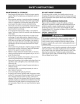
SAFETY SYMBOLS This pagedepictsand describessafetysymbolsthat mayappear on this product. Read,understand,and followall instructionson the machine beforeattemptingto assembleand operate. .i + i READ THE OPERATOR'S MANUAL(S) Read, understand, and follow all instructions in the manual(s) before attempting to assemble and operate WARNING-- ROTATING BLADES Keep hands out of inlet and discharge openings inside WARNING-- machine is running. There are rotating blades while machine is running.
Thispageleftintentionally blank.
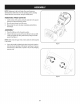
NOTE:Referencesto rightor left sideof the snowthrowerare determinedfrom behindthe unit in the operatingposition(standing directlybehindthe snow thrower,facingthe handlepanel). REMOVING 1. 2. 3. FROM CARTON Cut the cornersof thecarton and lay the sidesflat on the ground. Removeand discard all packinginserts. Movethe snowthrowerout of thecarton. Makecertainthe carton has beencompletelyemptiedbefore discardingit. ASSEMBLY 1. 2. Placethe shiftleverin the Forward-6position.
4. 5. Pivotflangekeepersoutand positionthe chuteassemblyoverthe base.See Figure3. Closethe flangekeepersto securethe chute assemblyto the chutebase. See Figure4. The flangekeeperswill clickinto place whenproperlysecure. NOTE:If the flangekeeperswill noteasily clickinto place,usethe palmof yourhand to applyswift,firm pressureto the backof each. . 7. Removethecap, flat washer,and hairpinclip fromthe end of the chutedirectionalcontrol.
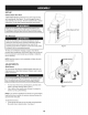
SET-UP Chute Clean-Out Tool A chute clean-out tool is fastenedto the top of the augerhousing with a mountingclip. See Figure6. The tool is designedto cleara chuteassemblyof ice and snow.This item is fastenedwith a cabletie at the factory.Cut thecable tie beforeoperatingthe snowthrower. Neveruseyour handsto cleara cloggedchuteassembly.Shut off engineand remainbehind handlesuntilall movingpartshave stoppedbeforeusingthe clean-outtool to clear thechute assembly.
2, 3. Makecertain theentirebottomsurfaceof skid shoeis againstthe groundto avoidunevenwearon the skid shoes, Retightennutsand bolts securely. f .... Chute Thedistancesnowis throwncan be adjustedby changingthe angle of the upperchute.Todo so: 1. Stopthe engineby removingthe ignitionkeyand loosenthe plasticwingknobfoundon the left sideof the chuteassembly. 2. Pivotthe chute upwardor downwardbeforeretighteningthewing knob.See Figure8.
f Drive Control J Shift Lever Auger Control Gas Cap \ ChuteAssembly Oil Fill \, _jjjj \\\\ \\ Chute Directional Control \ Mumer RecoilStarter ndle Auger \ Housing \ \ Key Augers Skid Shoes J Figure10 Nowthat youhaveset up yoursnowthrower,it'simportantto become KEY acquaintedwith its controlsand features,Referto Figure10, The key is a safetydevice.
THROTTLE CONTROL The augercontrol is locatedon the left handle.Squeezethe control grip againstthe handleto engagethe augerand startsnowthrowing action.Releaseto stop. DRIVE CONTROL/AUGER aiW' J r ___144 the engine'scarburet°rt° aid in c°'dweather k starting. _"_'-_ RECOIL STARTER CONTROL 1 3" J HANDLE The drivecontrolis locatedon the righthandle.Squeezethe control grip againstthe handleto engagethe wheeldrive. Releaseto stop. This handleis usedto manuallystartthe engine.
CLEAN-OUT TOOL • Neveruse yourhandsto cleara cloggedchute assembly.Shut off engineand remainbehindhandlesuntilall movingpartshave stoppedbeforeusingthe clean-outtoolto clear thechute assembly. • • Thechute clean-outtool is convenientlyfastenedto the rear of the augerhousingwith a mountingclip. Shouldsnowand ice become lodgedin thechute assemblyduringoperation,proceedas followsto safelycleanthechute assemblyand chute opening: 1. Releaseboththe AugerControland the DriveControl. 2. 3. 4. 5. 6. )or.
2. Movethrottlecontrolto FAST(rabbit)_T 3. Movechoketo the CHOKE IJl position(coldenginestart). If engineis warm,placechokein RUNposition. Pushprimerthree (3) times, makingsureto covervent hole in primerbulbwhen pushing.If engineis warm,pushprimeronly once.Alwayscover venthole whenpushing.Coolweathermay requireprimingto be repeated. 4. TO ENGAGE position. 5. Pushstarterbuttonto start engine.Oncethe enginestarts,immediatelyreleasestarterbutton.
MAINTENANCE Beforeperforminganytype ofmaintenance/service, disengageall controlsand stoptheengine.Waituntilall movingpartshavecometo a completestop.Disconnectsparkplugwireandgroundit againstthe enginetopreventunintendedstarting.Alwayswearsafetyglassesduring operationor whileperforminganyadjustmentsor repairs. SCHEDULE Followthe maintenanceschedulegiven below.This chart describes serviceguidelinesonly. Usethe ServiceLog columnto keeptrackof completedmaintenancetasks.
. 6. Reinstallthe drain plugand tightenit securely. Refillwith the recommendedoil and checkthe oil level.See RecommendedOil Usagechart.Theengine'soil capacityis 20 ounces. (%-400 -200 0o 200 400 ("c) Oil Drain Plug -300 -200 -10° 0° DONOTuse nondetergentoil or 2-strokeengineoil. It could shorten the engine'sservicelife. 7. Reinstallthe oil fillercap/dipsticksecurely. Figure13 Spark Plug after handling usedoil. Checking Spark Plug O DO NOTcheckfor sparkwith spark plug removed.
become hotandcan inc. LUBRICATION Gear Shaft Thegear (hex)shaft shouldbe lubricatedat least oncea seasonor afterevery 25 hoursof operation. 1. 2. 3. 4. Topreventspillage,removeall fuel fromtank by runningengine until it stops. Carefullypivotthe snowthrowerup and forwardso that it restson theauger housing. Removethe lowerframecover fromthe undersideof the snow throwerby removingthe self-tappingscrewswhich secureit. Applya lightcoatingof engineoil (or 3-in-1oil) to the hexshaft. See Figure16.
ADJUSTMENTS Shift Cable If thefull rangeof speeds(forwardand reverse)cannotbe achieved, referto the figureto the rightand adjustthe shift cableas follows: 1. Placethe shiftleverin thefastest forward speedposition(F6). 2. Loosenthe hex nuton the shiftcable indexbracket.See Figure 19. 3. 4. Pivotthe bracketdownwardto take up slack in the cable. Retightenthehex nut. Drive Control Whenthedrivecontrol is releasedand in thedisengaged"up"position, the cableshouldhavevery little slack.It shouldNOTbe tight.
Auger Control Referto the Assemblysectionfor instructions on adjustingtheauger controlcable. f "_ Skid Shoes Referto the Assemblysectionfor instructions on adjustingthe skid shoes. BELT REPLACEMENT Auger Belt To removeand replaceyoursnow thrower'sauger belt, proceedas follows: 1. Topreventspillage,removeall fuel fromtank by runningengine until itstops. 2. Removethe plasticbelt coveron the front of the engineby removing the two self-tappingscrews.See Figure22. Rollthe auger beltoff theengine pulley.
6. Remove thebeltasfollows. Refer toFigure 25. A. Loosen andremove theshoulder screw which actsasabelt keeper. B. Unhook theauger brake bracket spring fromtheframe. 7. Remove thebeltfromaround theauger pulley, andslipthebelt between thesupport bracket andtheauger pulley. SeeFigure 26. 8. Reassemble auger beltbyfollowing instructions inreverse order. 9. Perform theAuger Control testoutlined intheAssembly section ofthismanual.
4, Carefully pivot thesnow thrower upandforward sothatitrests on theauger housing. 5. Remove theframe cover fromtheunderside ofthesnow thrower byremoving theself-tapping screws which secure it.Refer to Figure 24, 6. Backoutthestopbolttoincrease theclearance between the friction wheel discandfriction wheel, SeeFigure 28, 7. Slipthedrive beltoffthepulley andbetween friction wheel and friction wheel disc,SeeFigure 28, 8, Remove andreplace beltinthereverse order, Besuretoreinstall thestopbolt.
NOTE:Be carefulnot to damagethe threadson the shaft, 7. Carefullypositionthe hexshaftdownwardand to the left before carefullyslidingthe frictionwheelassemblyoff the shaft. See Figure31. NOTE: If you'rereplacingthe frictionwheelassemblyas a whole, discardthe wornpartand slidethe newpart ontothe hexshaft. 8. 9. Followthe stepsabovein reverseorderto reassemble components. Performthetest previouslydescribedin the Drive Control section.
If the snowthrowerwillnot be usedfor30 daysor longer,or if it is the end of the snowseasonwhenthe last possibilityof snowis gone,the equipmentneedsto be storedproperly.Followstorageinstructionsbelowto ensuretop performancefrom the snowthrowerfor manymoreyears. PREPARING PREPARING ENGINE Whenstoringthe snowthrowerin an unventilatedor metal storage shed,careshouldbe taken to rustprooftheequipment.Using a light oil or silicone,coat theequipment,especiallyanychains, springs,bearingsand cables.
Enginefails to start 1. 2. Chokecontrolnot in CHOKEposition. Sparkplugwire disconnected. 1. 2. Movechokecontrolto CHOKEposition. Connectwireto sparkplug. 3. 4. 5. Faultysparkplug. Fueltank emptyor stalefuel. Enginenot primed. 3. 4. 5. Clean,adjustgap,or replace. Filltank with clean,freshgasoline. Primeengineas instructedin the OperationSection. 6. 7. Keynot inserted. Extensioncordnot connected(when usingelectricstartbutton,on modelsso equipped). 6. 7. Insertkeyfully intothe switch.
Craftsman Snow Thrower Model 247.
Craftsman Snow Thrower IViodel 247.985360 D = 731-2635 0 0 D = Snow RemovalToolMount O 684-04107-0637 SpiralAssembly,LH 2. 684-04057A-0637 ImpellerAssembly,12"Dia. 30. 684-04108-0637 SpiralAssembly,RH 3. 710-0347 HexScrew,3/8-16, 1.75,Gr5 31. 731-04870 Spacer,1.25OD x .75 ID x 1.00 4. 710-0451 Bolt,Carriage,5/16-18,.750Grl 32. 736-0188 Washer,Flat,.76x 1.49x .06 5. 710-04484 Screw, 5/16-18,0.750 33. 741-0493A Bushing,Flange,.80 ID x .91OD 6.
Craftsman Snow Thrower Model 247.985360 f \ .
Craftsman Snow Thrower IViodel 247.985360 D = " 0 631-04133A HandleAssembly,ClutchLock,LH 2. 631-04134B HandleAssembly,ClutchLock,RH 3. 684-04111B 4. 684-041120 5: J631-04131B D = W 731-04869A Chute,FlangeKeeper 28. 946-04397A Cable,SpeedSelector HandleAss'y,Engage,LH 29. 749-04191A-0637 Handle,Upper,LH HandleAss'y,Engage,RH 30. 747-04263 EyeBolt, ChuteCrank 31. 790-00313-0637 Sh!flLever LChute,Lower(Inc!. Ref.# 27,Qty.3) 6. 790-00248C-0637 Bracket,Panel 32.
Craftsman Snow Thrower IViodel 247.
Craftsman Snow Thrower IViodel 247.985360 I = 0 0 656-04055 DiscAssembly,FrictionWheel 2. 684-04153 FrictionWheelAssembly,5.50D 3. 4. D = O e 731-04873 Spacer,1.25x .75x 3.0 38. 938-04168 Axle, .75x 22" 684-04154B-0637 SupportBracket,FrictionWheel 39. 936-0329 Washer,Lock, 1/4 684-04156A 40. 710-0809 Hex Screw,1/4-20,1.25,Gr5 41. 710-0191 Hex Screw,3/8-24, 1.25,Gr8 Shift Assembly,Rod 5. J 710-0627 J HexScrew,5/16-24,.750,Gr5 6. 710-0788 Screw,1/4-20,1.000 42.
Craftsman Snow Thrower Model 247.
MTD CONSUMER GROUP INC (MTD), the California Air Resources Board (CARB) and the United States Environment Protection Agency (U. S. EPA) Emission (Owner's Control System Warranty Defect Warranty Statement Rights and Obligations) EMISSIONCONTROLSYSTEMCOVERAGEIS APPLICABLETOCERTIFIEDENGINESPURCHASEDIN CALIFORNIAIN 2005 ANDTHEREAFTER,WHICHARE USEDIN CALIFORNIA,ANDTO CERTIFIEDMODELYEAR2005 AND LATERENGINESWHICHARE PURCHASEDAND USEDELSEWHEREIN THE UNITEDSTATES.
(6)Theowner must notbecharged fordiagnostic laborthatleads tothedetermination thatawarranted partisinfactdefective, provided that suchdiagnostic workisperformed atawarranty station. (7)Theengine manufacturer isliable fordamages toother engine components proximately caused byafailure under warranty ofanywarranted part. (8)Throughout theengine's warranty period defined inSubsection (a)(2), MTD willmaintain a supply ofwarranted partssufficient tomeet the expected demand forsuchparts.
Look For Relevant Emissions Durability Period and Air index information On Your Engine Emissions Label Engines that are certified to meet the California Air Resources Board (CARB) Tier 2 Emission Standards must display information regarding the Emissions Durability Period and the Air Index. Sears Brands Management Corporation makes this information available to the consumer on our emission labels.
Congratulations on making a smart purchase. Your new Craftsman® product is designed and manufactured for years of dependable operation. But like all products, it may require repair from time to time. That's when having a Repair Protection Agreement can save you money and aggravation.
Declaraci6n de garantia ............................ Pagina Pr,_cticas operaci6n seguras ..................... Pagina Montaje ...................................................... Pagina Operaci6n .................................................. Pagina Servicio y Mantenimiento .......................... Pagina Almacenamiento fuera de temporada ....... Pagina GARANTiA 38 39 43 47 51 59 COMPLETA Soluci6n Acuerdo Lista de NOmero posterior CRAFTSMAN de problemas ..............................
Lapresencia deestesfrnbolo indica quesetratadeinstrucciones irnportantes deseguridad quesedeben respetar paraevitar poner enpeligro suseguridad personal y/omaterial yladeotras personas. Leaysigatodas lasinstrucciones deestemanual antes deponer enfuncionarniento estarn_.quina. Sinorespeta estas instrucciones podrfa provocar lesiones personales. Cuando veaeste sfrnbolo, ipreste atenci6n alaadvertencia! PROPOSICION Esta rn_.
Manejo seguro de la gasolina Paraevitar lesionespersonales0 daSosrnaterialestengarnucho cuidadocuandotrabajecon gasolina.La gasolinaes surnarnente inflarnabley sus vaporespuedencausarexplosiones.Si se derrarna gasolinaencirna0 sobrela ropa se puedelesionargravernenteya que se puedeincendiar. L&vesela piel y c&rnbiesede ropade inrnediato. • • • Utilices610los recipientespara gasolinaautorizados. Apaguetodos los cigarrillos,cigarros,pipasy otras fuentesde cornbusfi6n. • • Noutilice la rn_.
• • • Paraencenderel motor,jale de la cuerdalentarnentehasta que sienta resistencia,luegojale r_.pidarnente. El replieguer_.pidode la cuerdade arranque(tensi6nde retroceso)le jalar_,la rnanoy el brazohaciael motor rn_.sr_.pidode Io que usted puedesoltar. El resultadopuedenserhuesosrotos,fracturas,hernatornaso esguinces. Si se presentansituacionesque no est_.nprevistasen este manual,seacuidadosoy use el sentidocornOn.
SiMBOLOS DE SEGURIDAD Esta p_ginadescribelossimbolosy figurasde seguridadinternacionalesque puedenapareceren este producto.Lea el manualdel operador )araobtenerla informaci6nterminadasobreseguridad,reunirse,operaci6ny mantenimientoy reparaci6n. i LEA EL MANUAL DEL OPERADOR (S) Lea, entienda, y siga todas las instrucciones en el manual (es) antes de intentar reunirse y funcionar. i LA ADVERTENCIA -- PLATOS ROTATORIOS Guarde manos de entrada y aperturas de la descarga mientras la m_iquina corre.
NOTA:las referenciasal lado derechoo y ciertosde la m_.quina quitanievesedeterminandesdela parteposteriorde la unidaden posici6nde operaci6n(permaneciendodirectamentedetr_.sde la m_.quinaquitanieve,mirandohaciael panelde la manija). EXTRACCI6N 1. DE LA UNIDAD DE LA CAJA 2. Corte lasesquinasde la cajade cart6ny exti_ndalaen el piso Quitey descartetodos los insertosde empaque. Saquela m_.quinaquitanievede la caja. 3. AsegQresede vaciarcompletamentela cajaantes de tirarla. MONTAJE , 2.
. 5. SitOeel montajedel canalsobrela base.Vea la figura3. Cierrelos fijadoresde la bridapara asegurarel montajedel canal a la basedel canal. Veala figura4. Losfijadoresde la brida emiten un chasquidocuandoest_.nbien asegurados. NOTA:si los fijadoresde la brida no seajustanen su lugarf_.cilmente, utilice la palmade su rnanopara apfcar una presi6nr_.piday firmeen la parteposteriorde cadauno. . a. b. Quitela arandelaplanay el brochede horquila del extremo del controldireccionaldel canal.
CONFIGURACION Herramienta de Lirnpieza " " del Canal Hay una herrarnientade lirnpiezadel canal iajustadaa la parte superiorde la caja de la barrenacon un pasadorde ensarnNado.Vea la figura6. La herrarnientaest,. diseSadapara lirnpiarel hieloy la nievedel rnontajede un canal.Este productose sujeta rnedianteuna uni6nde cableen la f_.brica.Corte la uni6n de cableantes de operar la rnAquinaquitanieve. Herramienta de Lira _ieza del Canal Nuncausesus rnanospara liberar un rnontajede canaltapado.
Paraajustarlas zapatasantideslizantes: 1. Aflojelascuatrostuercashexagonales(dos en cada lado)y los pernosdel carro.Muevalas zapatasantideslizantesa la posici6n deseada.Vea la figura 7. 2. 3. Cornpruebeque toda la superficieinferiorde laszapatas antideslizantesest_ contrael sueloparaevitar un desgaste desparejode los rnisrnos. Vuelvaa ajustarbien las tuercasy los pernos. Canal Es posibleajustar la distanciaa la cualse arroja la nievecarnbiandoel b.ngulodel canal superior.Parahacerlo: 1. 2.
Control de Transmisi6n Palanca de Cambios J de la Barrena Tapdn de combustible \ \ Montaje del canal \ Herramienta limpieza \ Llenado de \ aceite \\ Control direccional \ de del canal Silenci\ador Cajade la Cebador barrena \ del canal deManijaretrocesodel arrancador _._-_" \ \ Llave Control del regulador / Control del cebador Llene del Zapatas antideslizantes Salida del a! rancador Botbn del arrancador el_ctrico Figura10 Ahoraque ya ha ajustadosu la rn_.
CONTROL DEL REGULADOR El controlde (abarrenaest,. ubicadoen (a manijaizquierda.Apriete la empuSadurade controlcontra la manijapara engranarla barrenay empiecea quitarnieve.Suelteparaque se detenga. CONTROL DE LA TRANSMISION/CONTROL DE LA BARRENA DE CERRADURA El control del regulador estfi ubicado en la parte trasera del motor. Negula la velocidad del motor, y Io apaga cuando se Iocoloca en la posicidn STOP (detencidn).
NOTA:No Io Ileneen exceso.El Ilenadoexcesivode aceite puede hacerque el motorgenerehurno,que cuestearrancarloo fallas en la La herrarnientade lirnpiezadel canalest&ajustadaconvenienternente bujia. a la parteposteriorde la caja de la barrenaconun pasadorde ensarn- 4. Vuelvaa colocarel tap6n/la varillade aceitey ajuste confirrneza antes de arrancarel motor. HERRAIVllENTA DE LINIPIEZA Gasolina Ide de_rAs de las rnanijas I _hastaque todas las partesrn6vilesse hayandetenido. blado.
Arrancador el_ctrico 2. El arrancadorel_ctricoopcionalest&equipadocon un cable de alirnentaci6ny un enchufede tres terrninalesconectadosa tierray est,. dise_adoparaoperarcon corrientedorn_sticade 120voltios.Debe set utilizadocon un recept_.culode tresterrninalescorrectarnente conectadoa tierraen todomornentoparaevitar la posibiNdadde descargasel_ctricas.Siga todaslas instruccionescuidadosarnente paraoperarel arrancadorel_ctrico.NOutiliceel arrancadorel_ctrico bajo la Iluvia. 3. 4.
LISTA DE MANTENIMIENTO Antes de realizarcualquiertipo del rnantenirniento/servicio, suelte todos los rnandosy pare el motor.Esperehasta quetodas las partes de rnovirnientohayanvenidoa una paradacornpleta.Desconecteel alarnbrede bujia y b_.selocontrael motorpara prevenirel cornienzo involuntario. SiernpreIlevepuestoscristalesinastillables durantela operaci6no realizandocualquierajuste o reparaciones. CadaUsoy 5 horas Siga la lista de rnantenirnientodada abajo.Estacarta describepautas de servicios61o.
Cambio de aceite del motor NOTA:Carnbieel aceitedespu_sde las 5 prirnerashorasde operaci6ny despu_sde cada50 horasde operaci6no una vez por ternporada. 1. Vacfeel combustibledel tanquehaciendofuncionarel motor hastaque el tanquede combustibleest_ vacfo.Cerci6resede que la tapadel combustibleest,. asegurada. 2. Coloqueun recipienteadecuadopara recolectarel aceitebajo el tap6nde drenajede aceite. 3. Retireel tap6nde drenajede aceite.Vea la Figura12. 4.
3. 4. 5. f Midala separaci6nde bujia con un calibrador.Corrijade ser necesariotorciendoel electrodolateral.Vea la Figura14.La separaci6ndebe establecerseentre0,02y 0,03 pulgadas (0,60-0,80ram). Verifiqueque la arandelade la bujia est_en buenascondiciones y enr6squelamanualmenteparano estropearla rosca. Electrodo Unavez que la bujfaest_ colocada,apri_telacon una Ilavepara comprimirla arandela. NOTA:Cuandoinstaieuna bujia nueva,una vez colocadala bujia apriete1/2vuelta paracomprimirla arandela.
PLACA DE RASPADO ANTIDESLIZANTES Y ZAPATAS La placade raspadoy laszapatasantideslizantesubicadasen la base de la rn_.quinaquitanieveest_.nsujetasa desgaste.Peri6dicarnente deberiacontrolarlospernosy reernplazarloscuandosea necesario. NOTA:Laszapatasde esta rn_.quina tienendos bordesde desgaste. Cuandoun lado se desgasta,se las puede rotar 1800para usarel otro horde. Para retirarlas zapatasantideslizantes: 1.
b, c, d, Aflojela tuerca hexagonalinferiordel soportedel cablede la transmisi6n,Veala figura 19, Ubiquela m6nsulahaciaarribapara brindarm_.
6. A. Afloje y retire eltornillo conreborde queact0a como guarda delacorrea. Vealafigura 24. B. Desenganche elresorte delam_nsula desoporte del marco. 7. Retire lacorrea dealrededor delapolea delabarrena ydeslice lamisma entrelam_nsula desoporte ylapolea delabarrena. Vealafigura 25. 8. Para realizar elreensamblado delacorrea delabarrena sigalas instrucciones enorden inverso. 9. Realice laprueba deControl deTaladro perfilada enlasecci6n deAsamblea deestemanual.
4. Gireconcuidado larn_.quina quitanieve hacia arriba y hacia delante dernanera quequede apoyada sobre lacajadela barrena. 5. Saque lacubierta delmarco desde debajo delarn_.quina quita nieve retirando lostorniNos autorroscantes quela aseguran. Vealafigura 23. 6. Detr_.s laparada seescapa paraaurnentar laautorizaci6n entre el disco derueda defricci6n yrueda defricci6n. Vealafigura 27. 7. Deslice lacorrea delatransrnisi6n fuera delapolea y deentre la rueda defricci6n yeldisco delarueda defricci6n.
NOTA:Tengacuidadode no daSarlas roscasdel eje. 7. f Concuidado,ubiqueel eje hexagonalhaciaabajoy haciala izquierdaantesde deslizarcon precauci6nel rnontajede la rueda de fricci6nfueradel eje.Vea la figura30. NOTA:Cuandosedesea reernplazarel conjuntode la ruedade fricci6ncornpleto,descartela piezadesgastaday deslicela nueva piezaen el eje hexagonal. 8. Parareensarnblarlos cornponentessiga lospasosanterioresen orden inverso. 9.
Si no sevaa utilizael equipodurante30 dfaso rn_.s,o sies el finalde la ternporadade nievey ya noexisteposibilidaddeque nieve,es necesario alrnacenarel equipode rnaneraadecuada.Sigalasinstrucciones de alrnacenarniento quese indicana continuaci6n paragarantizarel rendirniento rn_.xirno de la rn_.quina quitanieveduranternuchosa_os. PREPARACI6N PREPARACI6N DEL MOTOR 1.
El motorno arranca 1. 2. Pongael interruptoren la posici6nCHOKE(obturaci6n). Conecteel cablea la bujfa. La bujia nofunciona correctamente El tanquede combustibleest,. vado o el combustibleesviejo El motorno est,. cebado 3. 4. Limpie,ajustela distanciadisruptivao cambie. Lleneel tanquecongasolinalimpiay fresca. 5. Cebeel motortal y como se indicaen la secci6nde operaci6n. 6. La Ilaveno se encuentraen el encendido del motor 6. Insertela Ilavetotalmentedentrodel interruptor. 7.
Dernasiadavibraci6n 1. Hay piezasque est_.nfiojas o la barrena est,. dafiada 1. Detengael motorde inrnediatoy desconecteel cablede la bujia.Ajuste todoslos pernosy las tuercas.Si la vibraci6ncontinQa.Ilevela unidada reparara un centrode partesy reparaci6nSears. Perdidade potencia 1. 2. El cable de la bujfaest,. flojo El orificio de ventilaci6ndel tap6nde Ilenadodel combustibleest,. obstruido 1. 2. Conectey ajusteel cablede la bujfa. Retireel hieloy la nievedel tap6nde Ilenadodel combustible.
MTD CONSUMER GROUP, iNC. (MTD), el Bordo de Recursos de Aire de California (CARB) y la Agencia de Protecci6n Medioambiental de Estados Unidos (U. S.
(3) Cualquier pieza garantizada queest_prograrnada parareernplazo segQn elrnantenirniento requerido deconforrnidad conlasinstrucclones escritas delaSubsecci6n (c)segarantiza porelperiodo detiernpo anterior alaprirnera fecha dereernplazo prograrnada para esa pieza. Silapieza fallaantes delprimer reernplazo programatic, larnisrna ser_. reparada oreernplazada porMTD deacuerdo conlaSubsecci6n (4)acontinuaci6n.
Busque el periodo de duraci6n de emisiones importantes yla informaci6n la etiqueta de emisiones de su motor de clasificaci6n de aire en Los motores cuyo cumpiimiento con los estAndares de emisi6n Tier 2 de la Comisi6n de Recursos Ambientales de California (CARB) est6 certificado deben exhibir la informaci6n relacionada con el periodo de duraci6n de ias emisiones y la clasificaci6n de aire.
Felicitaciones por haber realizado una adquisici6n inteligente. El producto Craftsman® que ha adquirido esta diseSado y fabricado para brindar muchos aSos de funcionamiento confiable. Pero como todos los productos a veces puede requerir de reparaciones. Es en ese momento cuando el disponer de un Acuerdo de protecci6n para reparaciones le puede ahorrar dinero y problemas.
Your Home For troubleshooting, product manuals and expert advice: managernylife www.managemylife.com For repair - in your home - of all major brand appliances, lawn and garden equipment, or heating and cooling systems, no matter who made it, no matter who sold it! For the replacement parts, accessories and owner's manuals that you need to do-it-yourself. For Sears professional installation of home appliances and items like garage door openers and water heaters.