
Operator`s manual

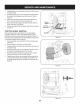


NOTE:Becarefulnot to damagethe threadson the shaft,
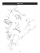
7. Carefullypositionthe hexshaftdownwardandto the left before
carefullyslidingthe frictionwheelassemblyoff the shaft.See
Figure31.
NOTE: Ifyou'rereplacingthe frictionwheelassemblyas a whole,
discardthe wornpartand slidethe newpart ontothe hexshaft.
8. Followthe stepsaboveinreverseorderto reassemble
components.
9. Performthetest previouslydescribedinthe DriveControl
section.
If you'redisassemblingthefrictionwheeland replacingonly the rubber
ring,proceedas follows:
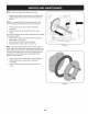
1. Removethefour screwswhichsecurethe frictionwheel'sside
platestogether. SeeFigure32.
2. Removethe rubberringfrombetweenthe plates.
3. Reassemblethe side plateswitha newrubberring.
NOTE: Whenreassemblingthe frictionwheelassembly,makesure
thatthe rubberringis centeredand seatedproperlybetweenthe side
plates.Tighteneachscrewonlyone rotationbeforeturningthe wheel
clockwiseandproceedingwiththe nextscrew.Repeatthisprocess
severaltimes toensurethe platesaresecuredwithequalforce
(between6 ft-lbsand 9 ft-lbs).
Figure31
4. Slidethe frictionwheelassemblybackonto the hexshaftand
followthestepsabovein reverseorderto reassemble
components.
5. Performthe testpreviouslydescribedin the DriveControl
section.
t j
Figure32
23