OPERATOR’S MANUAL Chipper Shredder Vacuum Model Number 24A-020D000 IMPORTANT: READ SAFETY RULES AND INSTRUCTIONS CAREFULLY Warning: This unit is equipped with an internal combustion engine and should not be used on or near any unimproved forestcovered, brush-covered or grass-covered land unless the engine’s exhaust system is equipped with a spark arrester meeting applicable local or state laws (if any). If a spark arrester is used, it should be maintained in effective working order by the operator.
TABLE OF CONTENTS Content Page Important Safe Operation Practices................................................................... 3 Assembling Your Chipper Shredder Vacuum .................................................... 5 Know Your Chipper Shredder Vacuum .............................................................. 7 Operating Your Chipper Shredder Vacuum ....................................................... 8 Maintaining Your Chipper Shredder Vacuum............................................
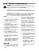
SECTION 1: IMPORTANT SAFE OPERATION PRACTICES WARNING: This symbol points out important safety instructions which, if not followed, could endanger the personal safety and/or property of yourself and others. Read and follow all instructions in this manual before attempting to operate this machine. Failure to comply with these instructions may result in personal injury. When you see this symbol - heed its warning.
i. Never store the machine or fuel container inside where there is an open flame, spark, or pilot light (e.g. furnace, water heater, space heater, clothes dryer, etc.) j. To reduce a fire hazard, keep machine free of grass, leaves, or other debris build-up. Clean up oil or fuel spillage and remove any fuel soaked debris. k. Allow machine to cool at least 5 minutes before storing. 9. Never operate without either the inlet nozzle or optional hose attachment properly attached to the machine.
WARNING - YOUR RESPONSIBILITY: Restrict the use of this power machine to persons who read, understand and follow the warnings and instructions in this manual and on the machine. NOTE: Not all safety labels shown may apply to your chipper shredder vacuum. SECTION 2: ASSEMBLING YOUR CHIPPER SHREDDER VACUUM IMPORTANT: This unit is shipped without gasoline or oil in the engine. Be certain to service engine with gasoline and oil as instructed in the separate engine manual before operating your machine.
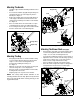
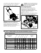
Attaching The Handle • • • • • Unfold the upper handle until it aligns with the lower handle. Secure the two handles by tightening the wing nuts (carriage bolts must be seated properly into the handle). See Figure 1. Remove the hairpin clips from the handle brackets on the chipper shredder vacuum and remove the carriage bolts and wing nuts from the lower handle. See Figure 2. Place each bottom hole in lower handle over pins on handle brackets and secure with hairpin clips.
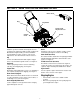
SECTION 3: KNOW YOUR CHIPPER SHREDDER VACUUM Blower Chute Bag Bag Handle Nozzle Height Adjustment Lever Chipper Chute Nozzle Figure 5 Nozzle Read this operator’s manual and safety rules before operating your chipper shredder vacuum. Compare the illustrations in Figure 5 with your unit to familiarize yourself with the location of various controls and adjustments. Save this manual for future reference. Yard waste such as leaves and pine needles can be vacuumed up through the nozzle for shredding.
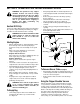
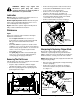
SECTION 4: OPERATING YOUR CHIPPER SHREDDER VACUUM WARNING: The operation of any chipper shredder vacuum can result in foreign objects being thrown into the eyes, which can damage your eyes severely. Always wear the safety glasses provided with this unit or eye shields before chipping or blowing and while performing any adjustments or repairs. • • • • Gas And Oil Fill-Up • Service the engine with gasoline and oil as instructed in the separate engine manual packed with your chipper shredder vacuum.
vines until they are thoroughly dried out. Materials such as stalks or heavy branches up to 1 1/2” in diameter may be fed into the chipper chute. See Figure 7. WARNING: Do not at any time make any adjustments without first stopping engine and disconnecting spark plug wire. Nozzle Height Adjustment The nozzle can be adjusted to any five positions, ranging from 5/8” to 4 1/8” ground clearance. The nozzle height has to be adjusted according to the conditions.
WARNING: Always stop engine and disconnect spark plug wire before cleaning, lubricating or doing any kind of maintenance on your machine. • • Lubrication • Wheels: Lubricate each wheel shoulder screw once a season with light oil. Refer to Figure 5. • Nozzle height adjustment levers: Lubricate the pivot points of the nozzle height adjustment levers once a season with light oil. Refer to Figure 5.
• • Remove the shoulder screws and bell washers that go through the pivot arms and height bracket adjusters to the front support brace. Remove the three screws on the upper housing that secure the nozzle cover and the nine screws that secure the lower housing to the upper housing. See Figure 12. • • • Housing Screw • • • • Apply lubricant to the threads of impeller removal tool and then thread the tool into the crankshaft. Stop when the impeller assembly can move on the crankshaft.
SECTION 6: TROUBLESHOOTING Problem Engine fails to start Cause Remedy 1. Spark plug wire disconnected. 2. Fuel tank empty or stale fuel. 3. Throttle control lever not in correct starting position. (If Equipped) 4. Choke not in CHOKE position. 5. Blocked fuel line. 6. Faulty spark plug. 1. Connect wire to spark plug. 2. Fill tank with clean, fresh gasoline. 3. Move throttle lever to FAST position. 1. Spark plug wire loose. 2. Unit running on CHOKE. 4. Water or dirt in fuel system. 5. Dirty air cleaner.
NOTES 13
Model 24A-020D000 1 2 3 39 4 5 12 6 11 10 8 7 9 13 14 13 17 19 18 15 7 16 20 5 7 21 16 22 23 25 24 26 27 30 28 31 29 32 33 34 35 36 36 37 38 36 14
Model 24A-020D000 Ref. No. 1. 2. 3. 4. 5. 6. 7. 8. 9. 10. 11. 12. 13. 14. 15. 16. 17. 18. 19. 20. Part No. 725-1700 725-3166 710-0224 629-0920 710-0604A 714-0104 736-0264 732-0962 781-0778A 747-1153 710-3008 681-0122 726-0454 736-0607 710-0502A 710-0969 710-3195 710-3025 710-0604A 781-1085 Ref. No. Part Description Switch Cover Safety Switch Hex Washer Screw #10-16 x.50 Wire Harness Hex Washer Screw 5/16-18 x.625 Cotter Pin Flat Washer.330 ID x.
Model 24A-020D000 1 2 4 30 5 3 6 8 7 10 9 12 11 13 31 14 9 16 11 9 32 19 20 22 15 23 25 18 16 17 14 28 21 29 27 24 26 16
Model 24A-020D000 Ref. No. 1. 2. 3. 4. 5. 6. 7. 8. 9. 10. 11. 12. 13. 14. 15. 16. Part No. 749-1423 720-0314 710-1174 749-0907B 664-0090 711-1293 712-0397 710-0703 726-0453 781-0777 712-3004A 714-0104 681-0155 681-0156 710-3025 736-0105 734-1987 Part Description Upper Handle Handle Knob 5/16-18 Carriage Bolt Lower Handle Bag Assembly Studs Wing Nut 1/4-20 Carriage Screw 1/4-20 x.
ÍNDICE Contenido Página Medidas importantes de seguridad.................................................................... 19 Montaje de la cortadora trituradora aspiradora ................................................. 21 Conozca las propiedades de la cortadora trituradora aspiradora....................... 22 Funcionamiento de la cortadora trituradora aspiradora ..................................... 23 Mantenimiento de la cortadora trituradora aspiradora .......................................
SECCIÓN 1: MEDIDAS IMPORTANTES DE SEGURIDAD ADVERTENCIA: La presencia de este símbolo indica que se trata de instrucciones importantes de seguridad que debe respetar para evitar poner en riesgo su seguridad personal y / o material y de otras personas. Lea y siga todas las instrucciones contenidas en este manual antes de intentar poner esta máquina en funcionamiento. De no hacerlo puede ocasionar lesiones. Cuando encuentre este símbolo - respete la advertencia que aparece a continuación del mismo.
2. 3. 4. Antes de encender la máquina compruebe que el canal de la cortadora, la toma de alimentación y la cámara de corte están vacías y sin escombros. Inspeccione minuciosamente todo el material que desea triturar y saque los objetos metálicos, piedras, botellas, latas u otros objetos extraños que pueden ocasionar lesiones o dañar la máquina. Si el motor golpea un objeto extraño o si la máquina produce un sonido poco común o una vibración al encenderla, apague el motor de inmediato.
SECCIÓN 2: MONTAJE DE LA CORTADORA TRITURADORA ASPIRADORA IMPORTANTE: Esta unidad se envía sin gasolina ni aceite en el Montaje de la manija motor. Antes de operar la máquina cargue el motor con gasolina y aceite como se indica en el manual separado del mismo. • NOTA: Las referencias a los lados derecho o izquierdo de la cortadora trituradora aspiradora se hacen observando la máquina desde la posición de operación.
• • • • Sostenga la manija de la bolsa con una mano y deslice la varilla de seguridad del soporte de montaje hacia el motor con la otra mano. Use el extremo del soporte de montaje como palanca cuando deslice la varilla de seguridad. Ver Figura 3. Deslice la bolsa por encima del borde de la abertura de descarga y suelte la varilla de seguridad para ajustar la bolsa en su lugar. Coloque las tiras de la bolsa por encima de la manija inferior enganchándolas en los pernos.
Canal de soplado (Si está incluido) Palanca de control del regulador (No se enseña) Cuando se lo une a la unidad el canal de soplado se utiliza para soplar o esparcir por los patios los desechos que se acumulan en los mismos como por ejemplo las hojas, las agujas de los pinos o las ramas pequeñas. Ver Figura 5. La palanca de control del regulador está ubicada en el motor. Controla la velocidad del motor y lo detiene.
• • • • • Gire los dos botones de la parte posterior de la bolsa para abrirla y vaciar el contenido. Ver Figura 6. Sostenga la manija y el broche de la bolsa mientras vacía el contenido. Comprima la abertura de la bolsa y doble la aleta interior sobre la abertura. Doble la aleta exterior sobre la aleta interior e inserte los botones de la bolsa a través de las salidas metálicas. Gire los botones para cerrar la bolsa.
• La bujía debe limpiarse y se debe reponer la distancia disruptiva una vez por temporada. Consulte el manual del motor para conocer las especificaciones para el tipo de bujía y para la distancia disruptiva. Limpie el depurador de aire cada 25 horas en condiciones normales o una vez por temporada. Limpie a intervalos de pocas horas cuando haya mucho polvo. Para realizar el control del depurador de aire consulte el manual separado del motor que viene embalado con la unidad.
• • • Montaje del brazo giratorio Arandela de campana Cuando afile las hojas, protéjase las manos mediante el uso de guantes y siga el ángulo original de molido. Para realizar el reensamblado siga los pasos anteriores pero en orden inverso. Ajuste los tornillos de la hoja con un par de torsión de 210-250 in-lbs. Ajuste el perno del motor con un par de torsión de 375-425 inlbs.
SECCIÓN 6: GUÍA PARA LA SOLUCIÓN DE PROBLEMAS Problema El motor no arranca Causa 1. 2. 3. 4. 5. 6. El motor funciona de manera errática Solución Se ha desconectado el cable de la bujía. El tanque de combustible está vacío o el combustible es viejo. La palanca de control del regulador no está en la posición de arranque correcta. (Si está incluida) La palanca de obturación no está en la posición CHOKE (obturación). La línea del combustible está bloqueada. La bujía no funciona correctamente. 1. 2.
DEL FABRICANTE GARANTÍA LIMITADA La garantía limitada que se extiende a continuación es otorgada por la empresa MTD PRODUCTS INC (“MTD”) con respecto a mercaderías nuevas compradas y utilizadas en los Estados Unidos, sus posesiones y territorios. MTD garantiza este producto por defectos materiales y de fabricación por un período de dos (2) años a partir de la fecha de la compra original y reparará o cambiará sin cargo cuando lo considere pertinente todas las piezas con defectos materiales o de fabricación.
MANUFACTURER’S LIMITED WARRANTY The limited warranty set forth below is given by MTD PRODUCTS INC (“MTD”) with respect to new merchandise purchased and used in the United States, its possessions and territories. MTD warrants this product against defects in material and workmanship for a period of two (2) years commencing on the date of original purchase and will, at its option, repair or replace, free of charge, any part found to be defective in material or workmanship.