Safety • Set-Up • Operation • Adjustments • Maintenance • Troubleshooting • Parts Lists • Warranty OPERATOR’S MANUAL Single-Stage Snow Thrower Model 230, S230 Model 240, S240 Model 250, S250 Model 260, S260 Model 261, S261 IMPORTANT READ SAFETY RULES AND INSTRUCTIONS CAREFULLY BEFORE OPERATION Warning: This unit is equipped with an internal combustion engine and should not be used on or near any unimproved forest-covered, brushcovered or grass-covered land unless the engine’s exhaust system is equipped
This Operator’s Manual is an important part of your new snow thrower. It will help you assemble, prepare and maintain the unit for best performance. Please read and understand what it says. Table of Contents Safety Labels ...................................................... 3 Safe Operation Practices ................................... 4 Set Up & Adjustment .......................................... 6 Know Your Snow Thrower .................................. 7 Operation...................................
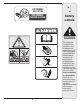
FOR TURNING, NOT LIFTING POUR TOURNER, PAS POUR LE LEVAGE 1 Safety Labels WARNING This symbol points out important safety instructions which, if not followed, could endanger the personal safety and/or property of yourself and others. Read and follow all instructions in this manual before attempting to operate this machine. Failure to comply with these instructions may result in personal injury. When you see this symbol.
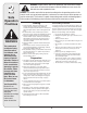
2 Safe Operation Practices WARNING This symbol points out important safety instructions which, if not followed, could endanger the personal safety and/or property of yourself and others. Read and follow all instructions in this manual before attempting to operate this machine. Failure to comply with these instructions may result in personal injury.
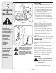
Operation Maintenance & Storage 1. Do not put hands or feet near rotating parts, in the auger/impeller housing or chute assembly. Contact with the rotating parts can amputate hands and feet. 2. The auger/impeller control lever is a safety device. Never bypass its operation. Doing so makes the machine unsafe and may cause personal injury. 3. The control levers must operate easily in both directions and automatically return to the disengaged position when released. 4.
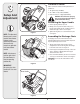
3 Contents of Carton Carton contents are listed below with part numbers in parentheses. 1. Two Ignition Keys (725-0201) 1 2. 2.6 oz Bottle of 2 Cycle Oil (737-04037) Setup And Adjustment 3. Extension Cord (if so equipped) (629-0236) WARNING: Disconnect the spark plug wire and ground it against the engine to prevent unintended starting. 2 Positioning the Upper Handle 1. Remove packing material, if present. 2.
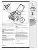
4 Auger Control Know Your Snow Thrower Electric Starter Button Figure 4A Starter Handle Key Fuel Cap Primer Chute Assembly Spark Plug Access Chute Handle Choke Lever Shave Plate Auger Figure 4 IMPORTANT: This unit runs on a mixture of gasoline and oil. Do NOT operate the snow thrower without first reading the engines operator’s manual for instructions regarding proper fuel and engine oil. Spark Plug Cover Remove spark plug cover to access spark plug.
5 Operation Before Starting Electric Starter(if equipped) WARNING: Before starting the engine, read, understand, and follow all instructions and warnings on the machine and in this manual. WARNING: The electric starter must be used with a properly grounded three-prong receptacle at all times to avoid the possibility of electric shock. Follow all instructions carefully prior to operating the electric starter. 1. The spark plug wire was disconnected for safety.
7. As engine warms up and begins to operate evenly, rotate choke lever slowly to the 1/2 Choke position. When the engine begins to run smoothly, move the choke to the OFF position. If engine falters, return to FULL choke, then slowly move to 1/2 then OFF position. To Stop Engine 1. To stop engine, turn ignition key counter-clockwise. Disconnect the spark plug wire from the spark plug to prevent accidental starting while equipment is unattended.
6 Shave Plate Side View Adjustments & Maintenance NOTE: On new units or units with a new shave plate installed, the augers may be slightly off the ground. 2. To adjust, tip the snow thrower back so that it rests on the handle. Loosen the lock nuts and bolts which secure the shave plate to the housing. See Figure 7. Move the shave plate to desired position and retighten the nuts and bolts securely.
Replacing Belt WARNING: Before servicing, repairing, or inspecting, disengage the control bail and stop engine. Wait until all moving parts have come to a complete stop. Disconnect spark plug wire and ground it against the engine to prevent unintended starting. Idler Pulley 6 Adjustments & Maintenance Remove the belt cover by removing five hex screws. See Figure 9. Then simply pull the belt off by grasping it from the bottom of the auger pulley and pulling off.
7 Off-Season Storage Observe the following, when preparing your snow thrower for off-season storage: • Drain fuel into an approved container outdoors, away from any open flame. Allow engine to cool. Extinguish cigarettes, cigars, pipes and other sources of ignition prior to draining fuel. Fuel left in engine during warm weather deteriorates and will cause serious starting problems.
Problem Cause Engine fails to start 1. Choke not in ON position. 1. Move choke to ON position. 2. Spark plug wire disconnected. 2. Connect wire to spark plug. 3. Fuel tank empty or stale fuel. 3. Fill tank with clean, fresh gasoline. 4. Engine not primed. 4. Prime engine as instructed in “Operating Your Snow Thrower”. 5. Faulty spark plug. 5. Clean, adjust gap, or replace. 6. Blocked fuel line. 6. Clean fuel line. 7. Safety key not in ignition on engine. 7. Insert key fully into the switch.
Models/Modèles 230-260 15 7 14 1 11 3 13 45 8 12 46 23 33 31 7 6 51 9 30 27 50 44 4 41 47 37 25 28 35 39 38 22 52 25 42 48 21 43 34 49 32 36 26 5 17 5 19 25 10 2 20 18 16 29 40 14 24
9 Models/Modèles 230-260 REF NO. N° DE RÉF PART NO.
Models/Modèles 230-260 �� �� �� �� �� �� �� � � � � � �� �� � � �� �� �� �� �� �� � �� �� � � �� �� �� �� �� �� �� �� �� 16 ��
9 Models/Modèles 230-260 REF NO. N° DE RÉF 1 2 3 4 5 6 7 8 9 11 13 14 15 16 17 18 19 20 21 22 24 25 27 28 29 30 31 32 33 34 35 36 37 PART NO.
10 Warranty Failure to comply with suggested maintenance and lubrication specifications will void warranty. TWO YEAR LIMITED WARRANTY The limited warranty set forth below is given by MTD LLC with respect to new merchandise purchased and used in the United States and/or its territories and possessions, and by MTD Products Limited with respect to new merchandise purchased and used in Canada and/or its territories and possessions (either entity respectively, “MTD”).