Operator’s Manual Single Stage Snow Thrower Models 285 & 295 Models E285 &E295 IMPORTANT: Read safety rules and instructions carefully before operating equipment. Warning: This unit is equipped with an internal combustion engine and should not be used on or near any unimproved forestcovered, brush-covered or grass-covered land unless the engine’s exhaust system is equipped with a spark arrester meeting applicable local or state laws (if any).
TABLE OF CONTENTS Content Page Important Safe Operation Practices .................................................................................. 3 Assembling Your Snow Thrower ....................................................................................... 5 Know Your Snow Thrower................................................................................................. 6 Operating Your Snow Thrower ..........................................................................................
SECTION 1: IMPORTANT SAFE OPERATION PRACTICES WARNING: This symbol points out important safety instructions which, if not followed, could endanger the personal safety and/or property of yourself and others. Read and follow all instructions in this manual before attempting to operate this machine. Failure to comply with these instructions may result in personal injury. When you see this symbol—heed its warning.
5. 6. 7. 8. 9. 10. 11. 12. 13. 14. 15. 16. 17. 18. 19. 20. Maintenance And Storage Never operate with a missing or damaged discharge chute. Keep all safety devices in place and working. Never run an engine indoors or in a poorly ventilated area. Engine exhaust contains carbon monoxide, an odorless and deadly gas. Do not operate machine while under the influence of alcohol or drugs. Muffler and engine become hot and can cause a burn. Do not touch.
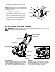
SECTION 2: ASSEMBLING YOUR SNOW THROWER Unpacking From Carton • • • • Cut along corners of the carton and lay it down flat. Remove packing material. Remove any loose parts included with unit (i.e., operator’s manual, etc.). Roll unit out of carton. Check carton thoroughly for any remaining loose part. • • Remove the hairpin clip from the end of the lower chute crank. Insert the upper chute crank into the lower chute crank and align the holes.
handle. Hold the “Z” fitting with the pliers, not the cable, to avoid damaging the cable. Lower Chute Nut NOTE: The upper hole in the control handle provides for adjustment in belt tension. Refer to page 9 of this manual for instructions. Carriage Bolt Flat Washer Flat Washer Assembling Discharge Chute • • • Hex Bolt Turn the chute crank until the chute faces straight to the front. See Figure 4 . Remove the hand knob, flat washer and carriage bolt from the upper chute. See Figure 4.
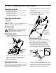
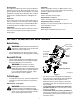
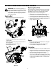
Discharge Chute Ignition Key The angle of the discharge chute controls the distance that the snow is thrown. Tilt the discharge chute up for greater distance; tilt down for less distance. Loosen the hand knob on the side of the discharge chute to adjust. Tilt the chute to the desired position, and tighten the knob. Used to start engine. Put key in “ON” position to start for both electric and recoil start engines. Follow starting instructions given in the next section.
• • • • • • If you have a grounded three-prong receptacle, proceed as follows. Rotate choke lever to FULL position. Connect power cord to switch box on dash panel. Plug the other end of power cord into a three-prong 120-volt, grounded, AC receptacle. Push starter button to crank engine. As you crank the engine, move choke lever to FULL choke position. When engine starts, release starter button, and move choke gradually to OFF. If engine falters, move choke immediately to FULL and then gradually to OFF.
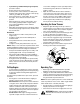
SECTION 5: MAKING ADJUSTMENTS Belt Tension WARNING: NEVER attempt to make any Periodic adjustment of the belt tension may be required due to normal stretch and wear on the belt. Adjust the belt tension, following instructions below, if the augers seem to hesitate while turning although engine maintains the same speed. adjustments while the engine is running, except where specified in the operator’s manual. Shave Plate • • To check the adjustment of the shave plate, place the unit on a level surface.
SECTION 6: MAINTAINING YOUR SNOW THROWER Replacing Shave Plate WARNING: Before servicing, repairing, or The shave plate is attached to the bottom of the auger housing and is subject to wear. It should be checked periodically. There are two wearing edges and the shave plate can be reversed. See Figure 14. inspecting, disengage all clutch levers and stop engine. Wait until all moving parts have come to a complete stop.
SECTION 7: OFF-SEASON STORAGE • • WARNING: Never store engine with fuel in tank indoors or in enclosed, poorly ventilated areas where fuel fumes may reach an open flame, spark or pilot light as on a furnace, water heater, clothes dryer, or other gas appliance. • • Follow “Storage” instructions in the Engine Manual. Store in a clean, dry area. Block the snow thrower up so it is not resting on the rubber auger blades.
SECTION 9: PARTS LIST FOR MODELS 285, 295, E285 AND E295 15 9 6 21 6 17 14 6 21 24 21 23 3 1 8 22 10 13 4 2 20 25 16 7 33 32 35 47 11 57 42 12 19 48 45 18 31 44 26 58 11 35 53 41 49 60 36 5 5 42 28 52 33 27 37 29 59 5 54 49 56 40 50 51 35 43 53 38 34 46 55 39 30 12
Models 285, 295, E285 and E295 Ref. No. 1. 2. 3. 4. 5. 6. 7. 8. 9. 10. 11. 12. 13. 14. 15. 16. 17. 18. 19. 20. 21. 22. 23. 24. 25. 26. 27. 28. 29. Part No. Part Description 747-1311 Upper Chute Crank Assemby 684-0177 Lower Chute Crank Assembly 684-0178 Bracket Assembly: Mitten Grip 731-2570 Shroud: Yellow, 7 Hp. Electric 731-2571 731-2607 710-0895 Shroud: Yellow, 5 Hp. Electric Shroud: Yellow, 5 Hp. Recoil TT Screw 1/4-15 x 0.75” 710-1003 B Screw #10-16 x 0.
Models 285, 295, E285 and E295 19 16 24 18 1 15 7 5 11 10 15 8 17 Engine is for reference only and may not resemble the engine on your snow thrower. 9 6 13 25 3 Part of electric start engines 21 13 23 14 3 2 4 22 Ref. No. 1. 2. 3. 4. 5. 6. 7. 8. 9. 10. 11. 13. Part No. 629-0236 Description Extension Cord † 710-0157 Hex Bolt 5/16-24 x 0.75” 710-0409 Hex Bolt 5/16-24 x 1.75” 710-0502A TT Sems Screw 710-0751 Hex Screw 1/4-20 x 0.620” 710-1003 B Screw #10-16 x 0.
Models 285, 295, E285 and E295 5 Ref. No. 9 8 10 3 2 4 Part No. Description 1. 710-0487 Carriage Screw 5/16-18 x 2.0” 2. 710-1270 Machine Screw 3. 712-0324 Hex Lock Nut 1/4-20 4. 720-0284 Hand Knob w/ Wing Nut 5. 720-0295 Foam Grip 6. 725-0157 Cable Tie 7. 736-0451 Saddle Washer 8. 746-0883 Control Housing 9. 747-0956 Auger Bail 749-0711A Upper Handle: Gull Wing 10. 1 6 7 7 4 5 Ref. No. 9 10 6 10 8 4 1 2 4 7 3 15 Part No. Description 1. 710-0276 2.
ÍNDICE Contenido Página Medidas importantes de seguridad ......................................................................................... 17 Montaje de su máquina quitanieve .......................................................................................... 19 Conozca la máquina quitanieve .............................................................................................. 20 Operación de su máquina quitanieve ......................................................................
ADVERTENCIA: Este símbolo indica importantes instrucciones de seguridad las cuales, en caso de no ser respetadas, podrían poner en peligro la seguridad del personal y/o sus bienes materiales y los de terceros. Lea y siga todas las instrucciones contenidas en este manual antes de intentar poner esta máquina en funcionamiento. De no hacerlo puede ocasionar lesiones. Cuando vea este símbolo—preste atención a la advertencia..
7. 8. 9. 10. 11. 12. 13. 14. 15. 16. 17. 18. 19. 20. Mantenimiento y almacenamiento No opere la máquina estando bajo los efectos del alcohol o de drogas. El silenciador y el motor se calientan y producen una quemadura. No los toque. Sea sumamente precavido cuando opere la máquina sobre una superficie con grava o cuando la cruce. Manténgase alerta por si se presentan peligros ocultos o tráfico. Tenga cuidado cuando cambie de dirección o cuando opere la máquina en pendientes.
SECCIÓN 2: MONTAJE DE LA MÁQUINA QUITANIEVE Desempaque de la caja de cartón • • • • Corte las esquinas de la caja de cartón y extiéndala en el piso. Quite el material de empaque. Quite cualquier parte suelta que se incluya con su unidad (por ejemplo, el manual del operador, etc.). Deslice la unidad hasta sacarla de la caja de cartón. Verifique cuidadosamente si en la caja queda alguna parte suelta. Reinserte la broche de horquilla en el agujero para asegurar las dos manivelas del canal. Ver Figura 2.
Montaje del canal de descarga • • • Canal inferior Gire la manivela del canal hasta que el canal esté ubicado hacia el frente. Vea Figura 4 . Quite la perilla manual, la arandela plana y el perno del carro del canal superior. Ver Figura 4. Gire el canal superior por encima del borde del canal inferior. Esto eliminará cualquier espacio entre los canales superiores e inferiores. Asegúrelo con las piezas metálicas que acaba de quitar.
Canal de descarga Llave de encendido El ángulo del canal de descarga controla la distancia a la cual se arroja la nieve. Incline el canal de descarga hacia arriba si quiere que la nieve sea arrojada a una distancia mayor; incline hacia abajo si quiere que la descarga se realice a menor distancia. Afloje la perilla manual del lado del canal de descarga para ajustarlo. Incline el canal hacia la posición deseada y ajuste a perilla. Se utiliza para encender el motor.
• • • • Conecte el cable de alimentación a la caja del interruptor en el tablero de instrumentos. Enchufe el otro extremo del cable de alimentación en un receptáculo de CA con conexión a tierra de tres terminales de 120 voltios. Presione el botón del arrancador para arrancar el motor con la manivela. A medida que intenta encender el motor con la manivela, mueva la palanca de obturación hacia la posición de obturación FULL.
SECCIÓN 5: REALIZACIÓN DE AJUSTES Tensión de la banda ADVERTENCIA: NUNCA intente realizar Es posible que se requieran ajustes periódicos de la tensión de la banda debido al estiramiento y al desgaste normal de la banda. Ajuste la tensión de la banda, siguiendo las instrucciones que aparecen debajo si las barrenas parecen temblar cuando giran a pesar de que el motor mantiene la misma velocidad,.
SECCIÓN 6: MANTENIMIENTO DE LA MÁQUINA QUITANIEVE Reemplace la placa de raspado ADVERTENCIA: Antes de realizar tareas de La placa de raspado está adosada al fondo de la barrena y puede desgastarse. Debe ser controlada de manera periódica. Hay dos bordes de desgaste ya que la placa de raspado puede ser invertida. Ver Figura 14. • Quite los cuatro pernos del carro y las tuercas de seguridad hexagonales que se adosan a la caja de la máquina quitanieve.
SECCIÓN 7: ALMACENAMIENTO FUERA DE TEMPORADA • ADVERTENCIA: Nunca almacene el motor con combustible en el tanque en un espacio cerrado y con poca ventilación donde los gases del combustible puedan alcanzar el fuego, chispas o una luz piloto como la que tienen algunos hornos, calentadores de agua, calefactores, secadores de ropa o algún otro dispositivo a gas. • • • Siga las instrucciones de la sección de “Storage” (almacenamiento) del manual del motor. Almacénela en un área despejada y seca.
Your Notes/Vuestro Apuntes 26
Your Notes/Vuestro Apuntes 27
MANUFACTURER’S LIMITED WARRANTY FOR: The limited warranty set forth below is given by MTD PRODUCTS INC (“MTD”) with respect to new merchandise purchased and used in the United States, its possessions and territories. MTD warrants this product against defects in material and workmanship for a period of two (2) years commencing on the date of original purchase and will, at its option, repair or replace, free of charge, any part found to be defective in material or workmanship.