Operator's Manual / // / // /i.
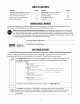
TABLEOFCONTENTS Content Page 3 6 8 10 13 Important Safe Operation Practices Assembling Your Snow Thrower Know Your Snow Thrower Operating Your Snow Thrower Making Adjustments Content Maintaining Your Snow Thrower Servicing Your Snow Thrower Troubleshooting Illustrated Parts List Page 15 15 20 22 Warranty Back Cover FINDINGMODELNUMBER This Operator's Manual is an important part of your new snow thrower. It will help you assemble, prepare and maintain the unit for best performance.
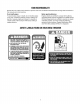
SECTION1: IMPORTANT SAFEOPERATION PRACTICES WARNING: Engine Exhaust, some of its constituents, contain or emit chemicals known to the State of California other reproductive harm. and certain vehicle components to cause cancer, birth defects or DANGER: This machine was built to be operated according to the rules for safe operation in this manual. As with any type of power equipment, carelessness or error on the part of the operator can result in serious injury.
Operation 18. Neverputyourhandinthedischarge orcollector openings. Alwaysusetheclean-out toolprovided to 1. Donotputhandsorfeetnearrotatingparts,inthe unclogthedischarge opening.Donotunclogchute auger/impeller housing or chuteassembly. Contact assemblywhileengineisrunning.Shutoffengine withtherotatingpartscanamputate handsand feet. andremainbehindhandlesuntilallmovingparts havestoppedbeforeunclogging. 2. Theauger/impeller controlisasafetydevice.Never andaccessories approved bypassitsoperation.
YOURRESPONSIBILITY Restrict the use of this power machine to persons who read, understand and follow the warnings and instructions in this manual and on the machine. Do not modifyengine To avoid serious injury or death, do not modify engine in any way. Tampering with the governor setting can lead to a runaway engine and cause it to operate at unsafe speeds. Never tamper with factory setting of engine governor.
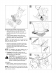
SECTION2: ASSEMBLING YOURSNOWTHROWER ........./t_ ........ NOTE: References to right or left side of the snow thrower are determined from behind the unit in the operating position (standing directly behind the snow thrower, facing the handle panel). NOTE: This Operator's Manual covers several models. Snow thrower features vary by model Not all features referenced and pictured in this manual are applicable to all snow thrower models.
Attachingthe Chute Assemblyand DirectionalControl 1. Apply a lubricant (i.e. 3-in-1 oil) to the rim of the chute base (and the underside of the chute assembly) and position the chute assembly over the base. 2. Close the flange keepers to secure the chute assembly to the chute base. The flange keepers will click into place when properly secure. NOTE: If the flange keepers wifl not easily click into place, use the palm of your hand to apply swift, firm pressure to the back of each.
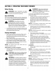
SECTION3: KNOWYOURSNOWTHROWER /4 Shift Lever Drive Control Chute Controlt Heated Handles Switcht Control Electric Starter Button f EngineControls Gas Recoil Starter Handle Oil Fill Electric Starter Outlet Chute Assembly \ Clean-out Tool Chute Directional Control Ignition Key Control Throttle Control Shoe Augers tlf Equipped ChokeControl _, all instructions and warnings on theand machine WARNING: Read, understand, follow and in this manual before operating.
AugerControl s Two-WayChuteControl(ifEquipped) f AUGER CONTROL _ CHUTE DiRECTiONAL CONTROL BISCHARGE_JBISCHARGE -- # The auger control is located on the left handle. Squeeze the control grip against the handle to engage the augers and start snow throwing action. Release to stop. DriveControl J = CHUTETiLT UP The two-way chute control is meant to control the distance of snow discharge from the chute. • To change the angle/distance which snow is thrown, pivot the joy-stick forward or backward.
SECTION4: OPERATING YOURSNOWTHROWER BeforeStarting WARNING: If your home electrical system is grounded, but a three-hole receptacle is not available, do not use your snow thrower's electric starter. all instructions and WARNING" Read,warnings understand, on theand machine follow and in this manual before operating.
IMPORTANT: Do not release the handle and allow it to snap back. Keep a firm hold on the starter handle and allow it to slowly recoil. • ToEngageDrive • As the engine warms, slowly rotate the choke control to the OFF position. If the engine falters, quickly rotate the choke control back to the FULL position and then slowly into the OFF position again. IMPORTANT:Use the slower speeds until you are comfortable and familiar with the operation of the snow thrower.
• Repeat Auger Control Test to verify proper adjustment has been achieved. Drift Cutters(onmodelssoequipped) Drift cutters should be used when operating the snow thrower in heavy drift conditions. On models so equipped, drift cutters are assembled to the auger housing inverted. Remove the carriage bolts by unthreading the hex nuts which secure them, and reinstall the drift cutters in their proper position before operating the snow thrower. See Figure 2.
SECTION5: MAKINGADJUSTMENTS • adjustments while WARNING: Nevertheattempt engineto ismake running, any except where specified in operator's manual. • ShiftRodAdjustment • If the full range of speeds (forward and reverse) cannot be achieved, refer to the figures marked 1,2, and 3 to the right and adjust the shift rod as follows: 1. 2. 3. Using a W' wrench, loosen the upper and lower hex nuts found on one cable adjuster.
DriveControl When the drive control is released and in the disengaged "up" position, the cable should have very little slack. It should NOT be tight. Check the adjustment of the drive control as follows: 1. 2. 3. With the drive control released, push the snow thrower gently forward. The unit should roll freely. Engage the drive control and gently attempt to push the snow thrower forward. The wheels should not turn. The unit should not roll freely.
SECTION6: MAINTAININGANDSERVICING YOURSNOWTHROWER WARNING: Before lubricating, repairing, or inspecting, disengage all controls and stop engine. Wait until all moving parts have come to a complete stop. Always wear safety glasses during operation or while performing any adjustments or repairs. Auger Shaft • At least once a season, remove the shear pins on auger shaft. Spray lubricant inside shaft, around the spacers. Also lubricate the flange bearings found at either end of the shaft. See Figure 9.
AugerBeltReplacement To remove and replace your snow thrower's auger belt, proceed as follows: 1. • • 2. Remove the plastic belt cover on the front of the engine by removing the two self-tapping screws. Drain the gasoline from the snow thrower, or place a piece of plastic under the gas cap. Carefully pivot the snow thrower up and forward so that it rests on the auger housing. Remove the frame cover from the underside of the snow thrower by removing four self-tapping screws which secure it. 3. 4.
DriveBeltReplacement To remove and replace your snow thrower's auger belt, proceed as follows: 1. • • 2. Remove the plastic belt cover on the front of the engine by removing the two self-tapping screws. Drain the gasoline from the snow thrower, or place a piece of plastic under the gas cap. Carefully pivot the snow thrower up and forward so that it rests on the auger housing. Remove the frame cover from the underside of the snow thrower by removing four self-tapping screws which secure it. 3. 4. • a.
FrictionWheelRemoval If the snow thrower fails to drive with the drive control engaged, and performing the drive control cable adjustment on page 14 fails to correct the problem, the friction wheel may need to be replaced. Follow the instructions below. Examine the friction wheel for signs of wear or cracking and replace if necessary • • • 1. Place the shift lever in third Forward (F3) position. Drain the gasoline from the snow thrower, or place a piece of plastic under the gas cap.
Augers • • IMPORTANT:NEVER replace the auger shear pins with anything other than OEM Part No.738-04124 replacement shear pins. Any damage to the auger gearbox or other components as a result of failing to do so will NOT be covered by your snow thrower's warranty. The augers are secured to the spiral shaft with two shear pins and cotter pins. If the auger should strike a foreign object or ice jam, the snow thrower is designed so that the pins may shear. Refer to Figure 9.
SECTION8: TROUBLE SHOOTING GUIDE Trouble Possible Cause(s) Engine fails to start Fuel tank empty, or stale fuel. Blocked fuel line. Choke control not in ON position Faulty spark plug. Ignition key not present. Spark plug wire disconnected. Engine not primed. Engine runs erratic Loss of power Engine overheats Excessive vibration Unit fails to propel itself Unit fails to discharge snow Unit running on CHOKE. Blocked fuel line or stale fuel. Water or dirt in fuel system. Carburetor out of adjustment.
NOTES 21
SECTION9: PARTSLIST 25 18b 9 _.. // 13 / 28_,. /// _ .......... 55 56<:T_ / 8 ......._ / / 66 ............................................................. / 48 _ 16 _(_ 58 ......... 57 18a 4O / / / / / / / i\ 41 2O 0 _59 51 _." .....
StylesH & K REF. PART NO. NO. 1 631-04125 631-04128 631-04133 631-04134 4 5 6 7 8 9 10 11 12 13 14 15a 15b 16 17 18a 18b 19 2O 21 22 23 24 25 26 27 28 29 30 31 684-04105 684-04106 710-04326 710-04354 710-1026 710-1233 711-04287 711-0677 712-04064 712-04081A 714-0104 720-0274 725-1757t 720-04039 725-04213 725-04214 725-04216At 725-1649 726-0470t 731-04894 731-04896 732-0193 732-04219 732-04238 735-0199A 736-0262 738-04122 738-04125 746-0778 747-04284 REF. DESCRIPTION Panel Assembly, Handle, H-Style* (Inc.
StylesH & K ForRemoteChute 69 ...... 7 _J _ z32 30 ForManualChute 1 11 39 14 22 6 8 4 6 35b 7 64 J 53 5 56_ 49 © 54 61 24 ....
StylesH & K REE NO. 1 2 3 4 5 6 7 8 9 10 11 12 13 14 15 16 17 18 19 20 21 22 23 24 25 26 PART NO.
StylesH & K 58 55 41 \ 5O 17 67 68 58 53 57 4O 47 52 49 45 51 48 43 56 21 13 s 24 29 18 12 27 14" 36 24 14 4_ 10 33 19 22 26 32 9 38 26 31 28" 37 25
StylesH & K REE NO. 1 2 3 4 5 6 7 8 9 10 11 12 13 14 15 16 17 18 19 20 21 22 23 24 25 26 27 28 29 30 31 32 33 34 PART NO.
MANUFACTURER'S LIMITED WARRANTY The limited warranty set forth below is given by MTD LLC with respect to new merchandise purchased and used in the United States, its possessions and territories. "MTD"warrants this product against defects in material and workmanship for a period of two (2) years commencing on the date of original purchase and will, at its option, repair or replace, free of charge, any part found to be defective in materials or workmanship.