Operator’s Manual Model Series 440 Thru E459 IMPORTANT: Read safety rules and instructions carefully before operating equipment. Warning: This unit is equipped with an internal combustion engine and should not be used on or near any unimproved forestcovered, brush-covered or grass-covered land unless the engine’s exhaust system is equipped with a spark arrester meeting applicable local or state laws (if any). If a spark arrester is used, it should be maintained in effective working order by the operator.
TABLE OF CONTENTS Content Page Important Safe Operation Practices................................................................... 3 Thru 5 Slope Gauge...................................................................................................... 6 Unpacking.......................................................................................................... 7 Assembling Your Lawn Mower........................................................................... 7 Know Your Lawn Mower .........
SECTION 1: IMPORTANT SAFE OPERATION PRACTICES WARNING: This symbol points out important safety instructions which, if not followed, could endanger the personal safety and/or property of yourself and others. Read and follow all instructions in this manual before attempting to operate your lawn mower. Failure to comply with these instructions may result in personal injury. When you see this symbol, heed its warning.
• • • • • • • • • • The blade control handle is a safety device. Never attempt to bypass its operation. Doing so makes the safety device inoperative and may result in personal injury through contact with the rotating blade. The blade control handle must operate easily in both directions and automatically return to the disengaged position when released. Never operate the mower in wet grass. Always be sure of your footing. A slip and fall can cause serious personal injury.
• • • • • To reduce fire hazard, keep mower free of grass, leaves, or other debris build-up. Clean up oil or fuel spillage. Allow mower to cool at least 5 minutes before storing. Before cleaning, repairing, or inspecting, make certain the blade and all moving parts have stopped. Disconnect the spark plug wire, and keep the wire away from the spark plug to prevent accidental starting. We do not recommend the use of pressure washers or garden hose to clean your unit.
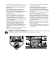
SECTION 2: SLOPE GAUGE FO L D ON D O TTE D 15° SIGHT AND HOLD THIS LEVEL WITH A VERTICAL TREE A POWER POLE A 15 ° S LOP E OR A FENCE POST A CORNER OF A BUILDING L I N E , RE PR E S ENT ING WARNING Do not mow on inclines with a slope in excess of 15 degrees (a rise of approximately 2-1/2 feet every 10 feet). A riding mower could overturn and cause serious injury.
SECTION 3: UNPACKING Removing Unit From Carton • • • • Remove staples, break glue on top flaps or cut tape at carton end and peel along top flap to open carton. Remove loose parts if included with unit (i.e., operator's manual, etc.). Cut corners and lay carton down flat. Remove packing material. Roll or slide unit out of carton. Check carton thoroughly for loose parts. NOTE: Make sure not to crimp the cables while removing the loose parts or the entire unit from the carton.
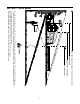
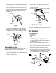
• • For shipping purposes, the hairpin clip is placed in the outer hole of the weld pin on the lower handle. Remove the hairpin clip from the outer hole of the weld pin. Using a pair of pliers, insert the hairpin clip into the inner hole in the weld pin. Repeat on other side. See Figure 4. • Slip the rope through the rope guide as shown below. Tighten the wing nut holding the rope guide to the upper handle.
HARDTOP GRASS BAG • • • • • • • B A Parts for Hardtop Grass Bag: Handle Rear Frame (packed inside hardtop cover) Front Frame Bag Hardtop Cover Mounting Bracket Hex Lock Nut Phillips Screw Black Plastic Bottom Assemble hardtop grass bag as follows: • Insert one end of the rear frame into the slit in the cloth channel on the edge of the grass bag (slits are approximately 6 inches from the end of the bag). See Figure 8A. Feed all the bag material on one side of the frame before working it around frame.
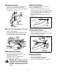
Attaching Grass Catcher Optional Chute Deflector • If your mower is equipped with the optional chute deflector, assemble as follows: If your mower is equipped with a mulching plug, and it is in place on the mower, lift the rear discharge door and remove the rear mulching baffle from the mower. See Figure 12. • • Slide the rod into the upper edge of the chute deflector so the tab on the rod is toward the left side of the chute deflector.
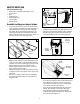
SECTION 5: KNOW YOUR LAWN MOWER Read this owner’s manual and safety rules before operating your lawn mower. Compare the illustrations in Figure 16 with your lawn mower to familiarize yourself with the location of various controls and adjustments. The operation of any lawn mower can result in foreign objects being thrown into the operator’s eyes thus causing severe eye damage. Always wear safety glasses while operating the mower, or while performing any adjustments or repairs on it.
Electric Start Ignition Switch (If Equipped) Ignition Switch If your mower is equipped with an electric starter, the ignition switch is located on the left side of the handle panel. It is used only for the electric starter. See Figure 17. Electric Start Units Only (Optional) Figure 17 SECTION 6: OPERATING YOUR LAWN MOWER Gas And Oil Fill-Up WARNING: Never fill fuel tank indoors, or when engine is running or hot. Do not smoke when filling up the fuel tank.
Starting Engine WARNING: Be sure no one other than the operator is standing near the lawn mower while starting engine or operating mower. • Never run engine indoors or in enclosed, poorly ventilated areas. Engine exhaust contains carbon monoxide, an odorless and deadly gas. • Keep hands, feet, hair and loose clothing away from any moving parts on engine and lawn mower. WARNING: If you strike a foreign object, stop the engine.
SECTION 7: MAINTAINING YOUR LAWN MOWER • Clean the engine periodically. Remove dirt and debris with a cloth or brush. • Clean the spark plug and reset the gap to.030” at least once a season or every 50 hours of operation. Spark plug replacement is recommended at the start of each season. Inspect muffler periodically, and replace if necessary. Damaged mufflers or spark arresters can create a fire hazard.
SECTION 8: SERVICE AND MAKING ADJUSTMENTS Blade Care • Periodically inspect the blade adapter and pulley for cracks, especially if you strike a foreign object. Replace when necessary. • WARNING: When removing the cutting blade for sharpening or replacement, protect hands by using heavy gloves or a thick rag to grasp the cutting blade. • • IMPORTANT: The bolt used to secure the blade to the engine is specially heat-treated. Do not substitute.
When replacing battery pack in handle panel, battery pack must be positioned with the positive terminal to the right hand side and the negative terminal to the left hand side of panel. Replacing the battery pack incorrectly will cause serious damage. The positive lead on the wire harness has the smaller connector. Connect the positive lead to the positive side of the battery pack, then connect the negative side.
• a. The mower does not propel itself with the drive control lever engaged. b. The mower’s drive wheels hesitate with the drive control lever engaged. To resolve the above problems, rotate the adjustment wheel with your fingers: clockwise to tighten the cable, and counter-clockwise to loosen the cable. See Figure 23 . • • Reassemble the upper handle to the lower handle.
SECTION 9: OFF-SEASON STORAGE Engine Prepare your lawn mower for storage at the end of the season or if the unit will not be used for 30 days or more. Store the mower in a clean, dry area. • Mower • • • • • • Clean underside of the mower following instructions in the Maintenance section of this manual. We do not recommend the use of pressure washers or garden hose to clean your unit. They may cause damage to electric components, spindles, pulleys, bearings or the engine.
SECTION 10: TROUBLE-SHOOTING GUIDE PROBLEM POSSIBLE CAUSE CORRECTIVE ACTION Engine fails to start 1. Blade control handle disengaged 2. Spark plug wire disconnected 3. Throttle control lever not in starting position 4. Fuel tank empty, or stale fuel 5. Blocked fuel line 6. Faulty spark plug 7. Engine flooded 1. Engage blade control handle 2. Connect wire to spark plug 3. Move throttle lever to correct position 4. Fill up tank with fresh gasoline 5. Clean fuel line 6. Clean, adjust gap, or replace 7.
SECTION 11: PARTS LIST FOR MODEL 440 THRU E450 SERIES 1 2 3 4 5 6 7 10 71 9 12 17 13 8 11 27 18 19 16 15 14 SEE ENGINE MANUAL 25 20 21 20 26 24 23 28 29 22 33 54 32 30 55 53 69 70 68 61 65 67 66 51 31 52 56 58 34 35 50 57 39 60 64 63 37 59 36 62 43 42 44 45 47 48 49 20 46 38 40 41
Models 440 Thru E450 Series Ref. No Part No.
Models 440 Thru E450 Series 1 2 51 3 55 39 40 5 46 47 53 4 7 8 45 48 43 42 6 9 52 41 38 13 11 10 36 35 32 14 49 30 31 30 33 31 19 39 33 32 47 12 40 52 15 53 16 51 17 34 41 37 20 36 42 44 43 21 20 19 22 25 23 29 24 54 26 28 50 27 28 22 46
Models 440 Thru E450 Series Ref. No 1. 2. 3. 4. 5. 6. 7. 8. 9. 10. 11. 12. 13. 14. 15. 16. 17. 18. 19. 20. 21. 22. 23. 24. 25. 26. 27. 28. Part No. Ref. No Description 712-3025 Hex Jam Nut 5/16-24 736-0425 Bell Washer .325 x .930 x .045 756-1042 Pulley, 3.82 x .313 x .68 736-0425 Bell Washer .325 x .930 x .045 712-0896 Lock Nut 1/4-28 736-0406 Flat Washer .442 x 1.38 x .
Models 440 Thru E450 Series 1 2 3 4 5 7 6 Electric Start (Optional) 8 12 13 15 10 9 16 11 9 25 14 17 20 21 18 19 23 24 22 26 31 30 32 29 28 27 24
Models 440 Thru E450 Series REF. NO. 1 2 3 4 5 6 7 8 9 10 11 12 13 14 15 16 17 18 PART NO. 725-0201 725-0873 731-0891A 725-0727 725-0298 725-1428 725-1276 710-0501 736-0270 712-0329 725-1206 712-0267 736-0242 712-0287 710-1250 710-0111 782-9012 710-0969 REF. NO. 19 20 21 22 23 24 25 DESCRIPTION Ignition Key Key Switch Battery Tray Battery Charger Fuse 7.5 Amp Fuse Holder Battery 12V Hex Screw:1/4-20:2.0 Bell Washer .265 x .75 x .062 Special Hex Nut 5/16-18 Plug Nut 5/16-18 Bell Wash .340 ID x .
SECTION 12: ENGINE SHROUDS Part No. Color 751B281439 Dark Red 751B281440 Black 751B281443 Bright Red Hardware: 710-1256 (Screw) Part No. Color 731-1585B Black Hardware: 710-1274 (Screw) Part No. 7511681311 7511681911 7511682011 Color Black Red Gray Part No. Color 731-1395A Red 731-1396A Black 731-1397A Gray Hardware: 710-1256 (Screw) Part No. Color 731-1402A Yellow 731-1694 Black 731-1695 Silver 731-1934 Charcoal Hardware: 710-1256 (Screw) Part No.
MANUFACTURER’S LIMITED WARRANTY FOR: The limited warranty set forth below is given by MTD PRODUCTS INC (“MTD”) with respect to new merchandise purchased and used in the United States, its possessions and territories. MTD warrants this product against defects in material and workmanship for a period of two (2) years commencing on the date of original purchase and will, at its option, repair or replace, free of charge, any part found to be defective in material or workmanship.