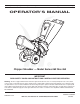
Safety • Assembly • Operation • Tips & Techniques • Maintenance • Troubleshooting • Parts Lists • Warranty OPERATOR’S MANUAL Chipper Shredder — Model Series 462 thru 464 IMPORTANT READ SAFETY RULES AND INSTRUCTIONS CAREFULLY BEFORE OPERATION Warning: This unit is equipped with an internal combustion engine and should not be used on or near any unimproved forest-covered, brushcovered or grass-covered land unless the engine’s exhaust system is equipped with a spark arrester meeting applicable local or state
This Operator’s Manual is an important part of your new chipper shredder. It will help you assemble, prepare and maintain the unit for best performance. Please read and understand what it says. Table of Contents Customer Support .............................................. 2 Safety Labels ...................................................... 3 Safe Operation Practices ................................... 4 Setting Up Your Chipper Shredder .................... 6 Operating Your Chipper Shredder ...........
������ ������ ������������������������ ������������������������ �� � � � �� � � �� � �� � �� ����������������������������������������������� � ������ ����� �� ������������������������������������������������� � ��������� �� ����������������������������������������������������� � �������������������������������������������� � ��������������������������������������������������� � ����������������������������������������������� � ��������������������������������������������� ��������� � �������������������
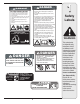
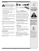
2 Safe Operation Practices WARNING This symbol points out important safety instructions which, if not followed, could endanger the personal safety and/or property of yourself and others. Read and follow all instructions in this manual before attempting to operate this machine. Failure to comply with these instructions may result in personal injury. When you see this symbol.
Operation Maintenance & Storage 1. Do not put hands and feet near rotating parts or in the feeding chambers and discharge opening. Contact with the rotating impeller can amputate fingers, hands, and feet. 2. Before starting the machine, make sure the chipper chute, feed intake, and cutting chamber are empty and free of all debris. 3.
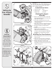
3 IMPORTANT: This unit is shipped without gasoline or oil in the engine. Be certain to service engine with gasoline and oil as instructed in the separate engine manual before operating your machine. � Loose Parts In Carton Setting Up Your Chipper Shredder d. Bag b. Chute Deflector e. Safety Glasses c. Chipper Chute f. Engine Oil Attaching The Hopper Assembly 1. a. Remove six hex nuts and washers from the weld studs on the impeller housing. Do not remove the support plate. See Figure 1. b.
3 b. Place second spacer over hex bolt inside other hinge and secure with hex lock nut. c. Secure both sides of chute deflector to impeller housing using wing knobs previously removed. Attaching The Chipper Chute � 5. a. Remove the three cupped washers and hex nuts from weld studs around the opening on the side of the impeller housing. See Figure 5. b. Remove the hex bolts, flat washers, and lock nuts from the two holes on the upper end of the support brace. 6. a.
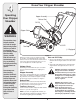
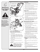
4 Know Your Chipper Shredder Operating Your Chipper Shredder ��������������� ����������� ��������� ������������� WARNING The operation of any chipper shredder can result in foreign objects being thrown into the eyes, which can damage your eyes severely. Always wear the safety glasses provided with this unit or eye shields before chipping or shredding and while performing any adjustments or repairs. Use extreme care when handling gasoline. Gasoline is extremely flammable and the vapors are explosive.
4 Starting Engine WARNING: Never run the engine indoors or in a poorly ventilated area. Engine exhaust contains carbon monoxide, an odorless and deadly gas. ���� 1. Attach spark plug wire to spark plug. Make certain the metal cap on the end of the spark plug is fastened securely over the metal tip on the spark plug. 2. Engines with choke lever: Move choke lever on engine to CHOKE position. (A warm engine may not require choking).
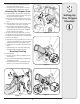
5 Lubrication 1. Lubricate the release rod and spring with light oil once a season. See Figure 11. ���������������� �������������� ����������� 2. Lubricate the pivot points on the hopper assembly with light oil once a season. See Figure 11. 3. Lubricate the pivot points on the discharge chute with light oil once a season. See Figure 11. Maintaining Your Chipper Shredder 4. Follow the accompanying engine manual for lubrication schedule and instruction for engine lubrication. Engine Care 1.
5 6. Remove the blade by removing the internal hex screws, lock washers, and hex nuts which secure it to the impeller. Retain the hardware. See Figure 13. NOTE: Use a 3/16” hex key (Allen) wrench on the outside of the blade and a 1/2” box (or socket) wrench on the inside of the impeller. Hold the Allen wrench stationary and rotate the box (or socket) wrench to loosen the nut. Maintaining Your Chipper Shredder 7. Install a replacement blade (Part No. 781-0490) with the hardware removed earlier or sharpen.
6 Problem Engine fails to start Trouble Shooting Engine runs erratic For repairs beyond the minor adjustments listed here, contact an authorized service dealer. Engine overheats Occasional skips (hesitates) at high speed Excessive Vibration Unit does not discharge Rate of discharge slows considerably or composition of discharged material changes Cause Remedy 1. Throttle lever not in correct starting position (if equipped). 1. Move throttle lever to FAST or START position. 2.
NOTES: Use this page to make notes and write down important information. For parts and/or accessories please call 1-800-800-7310, or 1-330-220-4683. www.mtdproducts.
Model Series 462 Thru 464 � � � � � �� � � � �� �� �� �� �� �� �� �� �� � � �� �� �� �� � �� � �� �� �� �� �� �� �� �� �� �� �� �� �� �� �� �� �� �� �� �� �� �� �� �� �� �� �� �� �� �� �� 14 �� �� �� �� ��
1. 736-0217 Lock Washer, 3/8 2. 714-0149B Cotter Pin 3. 681-0048 Wing Knob 5/16-18 4. 681-0094 Chute Deflector Assembly 5. 711-0835 Clevis Pin 6. 781-0457 Shredder Screen 7. 726-0211 U-Nut 5/16-18 8. 750-0793 Spacer 9. 712-3027 Hex Lock Nut 1/4-20 10. 712-3004A Hex Lock Nut 5/16-18 11. 736-0119 Lock Washer 5/16 12. 681-0117 Inner Impeller Housing Assembly 13. 710-3025 Hex Cap Screw 5/16-18 x.625 14. 710-0157 Hex Cap Screw 5/16-24 x.75 15. 781-0490 Chipper Blade 16.
Model Series 462 Thru 464 ���� ���� ��� �� � � �� � � � � ��� � � ��� �� � � � ��� ��� �� � �� � ��� � �� ��� ��� ��� ��� ��� �� �� �� ��� ��� �� ��� ��� ��� �� ��� † Model Series 464 †† Model 464G Only ‡ Model Series 462 ^ Models 462 & 464D * If Equipped 16
1. 728-0175 Pop Rivet 2. 731-1899 Chipper Shredder Chute 3. 735-0249 Chute Flap 4. 781-0633 Chute Flap Strip 5. 681-0068A Chipper Chute Assembly 6. 710-0751 Hex Cap Screw 1/4 -20 x.620 7. 712-3027 Hex Lock Nut 1/4-20 8. 710-0106 Hex Cap Screw 1/4-20 x 1.25 9. 736-0173 Flat Washer.28 ID x.74 OD 10. 736-0242 Bell Washer.340 ID x.872 OD 11. 712-3010 Hex Nut 5/16-18 12. 749-1004 Support Brace 13. 712-3004A Hex Lock Nut 5/16-18 14. 710-0805 Hex Cap Screw 5/16-18 x 1.
NOTES: Use this page to make notes and write down important information.
NOTES: Use this page to make notes and write down important information.
MANUFACTURER’S LIMITED WARRANTY FOR The limited warranty set forth below is given by MTD LLC with respect to new merchandise purchased and used in the United States, its possessions and territories. “MTD” warrants this product against defects in material and workmanship for a period of two (2) years commencing on the date of original purchase and will, at its option, repair or replace, free of charge, any part found to be defective in materials or workmanship.