OPERATOR'S MANUAL 22" Rotary Mowers Model Series 500 Thru 519 IMPORTANT: Warning: Read safety rules and instructions carefully This unit is equipped with an internal combustion before operating engine and should not be used on or near any unimproved covered, brush-covered or grass-covered land unless the engine's exhaust system is equipped with applicable local or state _aws (if any).
TABLEOFCONTENTS Content Page Maintaining Safety ............................................................................................. 3 Slope Gauge ...................................................................................................... 6 Assembling Your Lawn Mower ........................................................................... 7 Know Your Lawn Mower .................................................................................... 9 Operating Your Lawn Mower ..
SECTION1: MAINTAININGSAFETY This Warning symbol points out important safety instructions which if not followec, could endanger the personal safety and/or property of yourself and others. Read and follow all instructions in this manual before attempting to operate your lawn mower. Failure to comply with these instructions may result in personal injury. When you see this symbol, heed its warning. DANG Ell: Your lawn mower was built to be coerated according to the rules for safe operation in this manual.
• • • Do not mow on wet grass. Reduced footing could cause slipping. Never operate the mower in wet grass. Always be sure of your footing. A slip and fall can cause serious personal injury. Keep a firm hold on the handle and walk, never run, If you feel you are losing your footing, RELEASE THE BLADE CONTROL HANDLE IMMEDIATELY and the blade will stop rotating within three seconds. CHILDREN Tragic accidents can occur if the operator is not alert to the presence of children.
° Keepelinuts.bolts,andscrewstighttobesurethe equipment is in safe working condition. • Never tamper with safety devices. Check their proeer operation regularly. • After striking a foreign object, stop the engme, remove the wire from the spark plug, and thoroughly inspect the mower for any damage. Repair the damage before starting and operating {he mower Never attempt to make a wheel or cutting adjustment while the engine is running. height • Grass catcher comoonents are subject to wear.
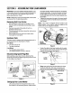
SIGHT AND HOLD THIS LEVEL WITH A VERTICAL TREE i< A POWER POLE A CORNER OF A BUILDING o OR A FENCE POST I £ o t0 0 E o _,1 o 15° WARNING 031D_ _ 0 .m ..c ,i= o 0 Do not mow on inclines with a slope in excess of 15 degrees (a rise of approximately 2-1/2 feet every 10 feet). A riding mower could overturn and cause serious injury. If operating a walk-behind mower on such a slope, it is extremely difficult to maintain your footing and you could slip, resulting in serious injury.
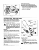
SECTION3: ASSEMBLING YOURLAWNMOWER IMPORTANT:This unit is shipped without gasoline or oil in the engine. Be certain to service engine with gasoline and oil as instructed in the separate engine manual before operating your mower, the lower handle is seated securely into the handle bracket assemblies. To secure the upper and lower handle, tighten the wing nuts near the toe of lower handle (carriage bolts must be seated properly into the handle).
Withthesparkplugwiredisconnected and grounded, holdthebladecontrolhandleagainstthe upperhandle,andpullthestarterropeoutofthe engine.Releasethebladecontrolhandle.Slipthe starterropeinto the rope guide. Tighten the wing RemovingChuteRetainer The chute deflector on your mower is held in an upright position by a retainer for shipping purposes only. Remove the retainer, following steps below, before running the mower for the first time, nut.
Installing Side DischargeChute If your mower is equippeo with the optional side discharge chute, install it following these instructions: Mulching Baffle Slide the hooks of the side discharge chute over the hinge pin on the mulching baffle, Make sure that the hooks snaps into place, locking the chute firmly onto the mower. See Figure 9. Release the mulching baffle.
SECTION5: OPERATINGYOURLAWNMOWER WARNING: Keep hands and feet away from chute area on the cutting deck. The operation of any lawn mower can result in foreign objects being thrown into the eyes, which can result in severe eye damage. Always wear safety glasses or eye shields. UsingYourLawnMower Be sure that the lawn is clear of stones_ sticks, wire, or other objects which could damage the lawn mower or the engine.
* Height Adjustment..._ • Lever Position each handle bracket assembly stud into one of the other holes in the lower handle. Each end of the lower handle must be placed in same relative position. Lower Figure 11 HandleHeightAdjustment Handle Bracket Assemblies Your mower is shipped with the handle in the higher height position. To lower the he ght proceed as follows: • • Remove the starter rope from the rope guide. Disconnect the handle from the handle bracket assemblies by removing the wing nuts.
Some adjustments will have to be made periodically to maintain your unit properly. All adjustments in the Making Adjustments section of this manual should be checked at least once each season. Periodically check all fasteners and make sure these are tight. Follow the maintenance schedule under Customer Engine Refer to the separate engine manual for all engine maintenance instructions. • Maintain engine oil as instructed in the separate engine manual packed with your unit.
° When sharpening the blade, follow the original angle of grind as a guide. It is extremely important that each cutting edge receives an equal amount of grinding to prevent an unbalanced blade. An unbalanced blade wilt cause excessive vibration when rotating at high speeds. It may cause damage to the mower, and could break causing personal injury. • • The blade can be tested by balancing it on a round shaft screwdriver, Remove metal from the heavy side until it balances evenly.
Models500 thru519 6 12 45 !8 31 \ 14
Models500 thru519 Ref. No. Ref, PaN No, NO, Part No. Part Description 1, 747-1161 Blade Control Handle 2. 749-1092 3_ 746-0957 Upper Handle Control Cable - B&S 25. 26. 746-1091 Control Cable - Tec 27. 736-0524A 738-1126 710-1205 Eye Bolt 28. 736-0105 734-1988 738-0102 Wheel Comp 7 x 1.8 Shoulder Screw 3/8 - 16 4. 742-0742 710-1044 , Mulching Blade 22" Hex Cap Screw 3/8-24 x 1.5 Blade Bell Support Shoulder Screw 3/8 - 16 x .302 I Bell Washer .401 ID x .870 OD 5.
MANUFACTURER'S LIMITED WARRANTY FOR: YARD The limited warranty set forth below is given by MTD PRODUCTS INC ("MTD") with respect to new merchandise purchased and used in the United States, its possessions and territories. MTD warrants this product against defects in material and workmanship for a period of two (2) years commencing on the date of original purchase and will, at its option, repair or replace, free of charge, any part found to be defective in c.