YARD OPERATOR'S MANUAL Log Splitter Vertical Shaft Assembled Model Series 500, 501,510, 511 530, 550, 560, and 561 MTD Jililililili _,,_i_, !_:, ,_!_!_: i::,!!:/, i i,_i ,_!_,,,, ,_, ,',,! Siiii,:i,_,_, !:,:_,, ,_i ,_i!i!i!i!i!i !i__!iiiilil __!i!i!i!! _:i!i!i!i! _I, IMPORTANT: READ SAFETY RULES AND INSTRUCTIONS CAREFULLY Warning: This unit is equipped with an internal combustion engine and should not be used on or near any unimproved forestcovered, brush-covered or grass-covered land unless the eng
TABLEOFCONTENTS Content Page Important Safe Operation Practices ................................................................... 3 Assembling Your Log Splitter ............................................................................. 5 Know Your Log Splitter ...................................................................................... 7 Operating Your Log Splitter ................................................................................ 8 Adjusting Your Log Splitter ........
SECTION1: IMPORTANT SAFEOPERATION PRACTICES WARNING: This symbol points out important safety instructions which, if not followed, could endanger the personal safety and/or property of yourself and others. Read and follow all instructions in this manual before attempting to operate this machine. Failure to comply with these instructions may result in personal injury. When you see this symbol - heed its warning.
g. To avoid personal injury or property damage use extreme care in handling gasoline. Gasoline is extremely flammable and the vapors are explosive. Serious personal injury can occur when gasoline is spilled on yourself or your clothes which can ignite. Wash your skin and change immediately. a. Use only an approved gasoline container. b. Extinguish all cigarettes, cigars, pipes, and other sources of ignition. c. Neverfuel machine indoors. d. e. f. g. h. i. j.
. For your safety, replace all damaged or worn parts immediately with original equipment manufacturer's (O.E.M.) parts only. "Use of parts which do not meet the original equipment specifications may lead to improper performance and compromise safety!" g. Do not alter this machine in any manner, alterations such as attaching a rope or extension to the control lever, or adding to the width or height of the wedge may result in personal injury.
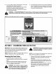
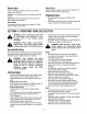
Bracket Tongue Assembly Horizontal @ Vertical Hex Bolts Hex Nuts Lock Washers Beam Lock Figure 3 Figure 1 Remove the spring clip and clevis pin from the jack stand. Pivot the jack stand to the operating position and secure with spring clip and clevis pin. See Figure 2. Clevis Pin -_= Tongue E]_f[ Assembly Preparing TheLogSplitter Lubricate the beam area where the splitting wedge will slide with engine oil (DO NOT USE GREASE). Remove reservoir vent plug. See Figure 4.
If not already, disconnect the spark plug wire and prime the pump, by pulling the recoil starter to turn the engine over approximately 10 times. Refill tank to within 3" to 3 1/2" from the top of the fill tube. Extend and retract the wedge 12 complete cycles to remove trapped air in the system (system is "selfbleeding"). Refill the reservoir to within 3" to 3 1/2" from the top of the fill tube. Much of the original fluid has been drawn into the cylinder and hoses.
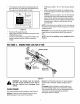
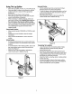
BeamLocks There are two beam locks one for each operating position. See Figure 6. Vertical: The vertical beam lock is located next to the oil filter. Horizontal: The horizontal beam lock is part of the beam support latch bracket. Starter Handle EngineControls See the separate engine manual for the location and function of the controls on the engine. Stopping Engine Move throttle control lever to STOP or OFF position. Disconnect spark plug wire and ground against the engine to prevent unintended starting.
UsingTileLogSpliUer Place the log splitter on level, dry, and solid ground. Place the beam in either the horizontal or vertical position and lock in place with the appropriate locking rod. Block the front and back of both wheels. Place the log against the end plate and only split wood in the direction of the grain. When necessary to stabilize the log, place your hand only on sides of log. NEVER place hand on the end between the log and splitting wedge.
SECTION5: ADJUSTING YOURLOGSPLITTER WARNING: Do not at any time make any adjustments without first stopping engine, disconnecting spark plug wire, and grounding it against the engine. WedgePlateAdjustment As normal wear occurs, adjust the bolts on the side of the wedge plate to eliminate the excess space between the wedge plate and beam. See Figure 9. Loosen the jam nuts on the two adjustment bolts on the side of the gib plate.
Set .010" to .060" clearance between the nylon "spider" and the engine coupling half by sliding a matchbook cover between the nylon "spider" and the engine coupling half and moving pump coupling half as needed. Secure pump coupling half with set screw. See Figure 10. Engine Refer to the separate engine manual for all engine maintenance instructions. FlexiblePumpCoupler The flexible pump coupler is a nylon "spider" insert, located between the pump and engine shaft.
SECTION7: CONDITIONS THATWILLVOIDWARRANTY Failure to maintain proper fluid level in reservoir will cause permanent damage to pump by allowing air to be drawn into pump. Fluid will become foamy. Changing the relief valve setting or pressure adjustment of control valve without proper knowledge and instruction from the factory will void your warranty. A very minor adjustment could destroy the structural and safety limits for which the unit was designed.
SECTION9: HYDRAULIC TROUBLESHOOTING Problem Cylinder rod will not move Cause Remedy 1. Broken drive shaft. 1. See authorized service dealer. 2. Shipping plugs left in hydraulic hoses. 2. 3. 3. 4. Set screws in coupling not adjusted properly. Loose shaft coupling. 5. 6. 7. 8. Gear sections damaged. Damaged relief valve. Hydraulic lines blocked. Incorrect oil level. 5. 6. Disconnect hydraulic hoses, remove shipping plugs, reconnect hoses. See operator's manual for correct adjustment.
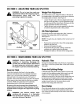
ModelSeries500, 501,510,511,530, 550, 560, and561 15 16 19 20 5 6_ _ 18 11 24 25_ 48 46 C 40 \ 60 "31 35 58 74 78 8O 77 14 56
ModelSeries500, 501,510,511,530, 550, 560, and561 Re_ No. Part No. Ref. No. Part Description Part Description Part No. 1. 2. 781-0323B 712-0239 Wedge Assembly Lock Nut 1/2-20 42. 43. 736-0159 736-0119 Washer 5/16 t 3. 710-1018 4. 736-0192 Hex Cap Screw 1/2-20 x 2,75 Flat Washer ,531 ID x ,93 OD 44. 45. 712-0123 710-0654A Hex Nut 5/16-24 t Hex Washer Screw 3/8-16 x 1.0 Hose Clamp Suction Hose Lock Washer 5/16 t 5. 710-0459A Hex Cap Screw 3/8-24 x 1,5 46. 726-0174 6.
MANUFACTURER'S LIMITED WARRANTY FOR: YARD The limited warranty set forth below is given by MTD PRODUCTS INC ("MTD") with respect to new merchandise purchased and used in the United States, its possessions and territories. MTD warrants this product against defects in material and workmanship for a period of two (2) years commencing on the date of original purchase and will, at its option, repair or replace, free of charge, any part found to be defective in material or workmanship.