
Manual


Engine
Refer to the separate engine manual for all engine
maintenance instructions.
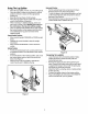
FlexiblePumpCoupler
The flexible pump coupler is a nylon "spider" insert,
located between the pump and engine shaft. Over a
period of time, the coupler will harden and deteriorate.
Replacement is needed if you detect vibration or noise
coming from the area between the engine and the
pump. If the coupler fails completely, you will
experience a loss of power.
IMPORTANT: Never hit the engine shaft in any manner,
as a blow will cause permanent damage to the engine.
When replacing the flexible pump coupler, proceed as
follows: I_
Remove three nuts and lock washers that secure
the pump to the coupling shield. Two nuts are at the
bottom corners and one is in the top center.
Remove the pump.
Rotate the engine by pulling starter handle until
engine coupling half set screw is at bottom. Loosen
set screw using allen wrench and slide coupling half
off of engine shaft.
Loosen set screw on pump coupling half and
remove coupling half.
Slide new engine coupling half onto the engine
shaft until the end of the shaft is flush with the inner
portion of the coupling half. (There must be space
between end of the engine support bracket and ,_
coupling half). Tighten set screw.
Install pump coupling half and key on pump shaft.
Rotate coupling half until set screw faces down. Do
not tighten set screw.
Install nylon "spider" onto engine coupling half. ,£t
Align pump coupling half with nylon "spider" by
4Jl=
rotating engine using starter handle. Slide coupling
half into place while guiding three mounting bolts
through holes in pump support bracket.
Secure with nuts and washers removed earlier.
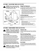
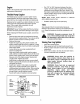
Gear Pump
Set
Nylon Steel
Insert Halves
Engine
Figure 10
Set .010" to .060" clearance between the nylon
"spider" and the engine coupling half by sliding a
matchbook cover between the nylon "spider" and
the engine coupling half and moving pump coupling
half as needed. Secure pump coupling half with set
screw. See Figure 10.
NOTE: Make certain proper clearance is obtained
before tightening set screw.
Reattach spark plug wire to spark plug.
Tires
See sidewall of tire for recommended pressure.
Maximum tire pressure under any circumstances is30
p.s.i. Equal tire pressure should be maintained on all
tires.
WARNING: Excessive pressure (over 30
p.s.i.) when seating beads may cause tire/
rim assembly to burst with force sufficient
to cause serious injury.
StoringYourLogSplitter
Clean the unit thoroughly.
Wipe equipment with an oiled rag to prevent rust.
Refer to engine manual for correct engine storage
instructions.
Store unit in a clean, dry area. Do not store next to
corrosive materials such as fertilizer.
WARNING: Never store the machine or
fuel container indoors where there is an
open flame, spark, or pilot light such as on
water heater, furnace, clothes dryer, or
other gas appliance.
WARNING: Drain fuel into an approved
container outdoors, away from an open
flame. Allow engine to cool. Extinguish
cigarettes, cigars, pipes, and other
sources of ignition prior to draining fuel.
Fuel left in engine for extended periods
deteriorates and will cause starting
problems.
11