YARD OPERATOR'S MANUAL Automatic Lawn Tractor Models 607 6O8 6O9 Model 608 Shown IMPORTANT: READ SAFETY RULES AND INSTRUCTIONS CAREFULLY Warning: This unit is equipped with an internal combustion engine and should not be used on or near any unimproved forestcovered, brush-covered or grass-covered land unless the engine's exhaust system is equipped with a spark arrester meeting applicable local or state laws (if any), If a spark arrester is used, it should be maintained in effective working order by t
SECTION 1: TABLE OF CONTENTS FINDING YOUR MODEL NUMBER ....................................................... CALLING CUSTOMER SUPPORT ........................................................ IMPORTANT SAFE OPERATION PRACTICES.............................................. SAFETY LABLES FOUND ON YOUR UNIT................................................. SLOPE GAUGE ...................................................................... ATTACHMENTS & ACCESSORIES .............................................
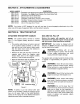
SECTION 4: IMPORTANT SAFE OPERATION PRACTICES WARNING: THIS SYMBOL POINTS OUT IMPORTANT SAFETY INSTRUCTIONS WHICH, IF NOT FOLLOWED, COULD ENDANGER THE PERSONAL SAFETY AND/OR PROPERTY OF YOURSELF AND OTHERS. READ AND FOLLOW ALL INSTRUCTIONS IN THIS MANUAL BEFORE ATTEMPTING TO OPERATE YOUR LAWN MOWER. FAILURE TO COMPLY WITH THESE INSTRUCTIONS MAY RESULT IN PERSONAL INJURY. WHEN YOU SEE THIS SYMBOL, HEED ITS WARNING.
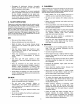
• Disengage all attachment clutches,thoroughly 3. CHILDREN depressthe brakepedal,andshiftinto neutral Tragic accidents can occur if the operator is not alert to the before attempting tostartengine. presence of children. Children are often attracted to the • Yourmoweris designed tocutnormalresidential machine and the mowing activity. Never assume that chilgrassofa heightnomorethan10".Donotattempt dren will remain where you last saw them. to mowthroughunusually tall, dry grass(e.g.
• Keepallnuts,boltsandscrews tightto besurethe equipment isinsafeworking condition. • Nevertamperwithsafetydevices.Checktheir properoperationregularly.Use all guardsas instructed inthismanual. • Afterstrikinga foreignobject,stopthe engine, remove thewirefromthesparkplugandthoroughly inspectthe mowerfor anydamage.Repairthe damage before restarting andoperating themower. • Grasscatchercomponents are subjectto wear, damageanddeterioration, whichcouldexpose movingpartsor allowobjectsto bethrown.
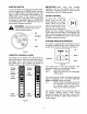
USE THIS PAGE AS A GUIDE TO DETERMINE SLOPES WHERE YOU MAY NOT OPERATE SAFELY. SIGHT AND HOLD THIS LEVEL WITH A VERTICAL TREE O m 15 ° _WARNING Do not mow on inclines with a slope in excess of 15 degrees (a rise of approximately 2-1/2 feet every 10 feet). A riding mower could overturn and cause serious injury. If operating a walk-behind mower on such a slope, it is extremely difficult to maintain your footing and you could slip, resulting in serious injury.
SECTION 5: ATTACHMENTS MODEL NUMBER OEM-190-601 OEM-190-602 OEM-190-112 OEM-190-118 OEM-190-603 OEM- 190-604 OEM-190-822 OEM-190-823 & ACCESSORIES DESCRIPTION FastAttach" Twin Bagger Grass Collector (For 42-inch Decks Only) FastAttach" Twin Bagger Grass Collector (For 46-inch Decks Only) Mulch Kit (For 42-inch Decks Only) Mulch Kit (For 46-inch Decks Only) FastAttach" Grille Guard" (mounts on front of tractor) YardMate" Storage Container (mounts on rear of tractor) FastAttach" 46-inch Front Dozer Blade
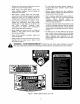
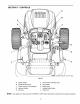
SECTION 7: CONTROLS D B F c\ A G J I NOTE: Steering Wheel not shown for clarity Figure 3 NOTE: A B Ignition Switch Throttle Control Lever F G PTO (Power Take-Off) Lever Drive Pedal C Choke Control (if so equipped) H Brake Pedal D E Indicator Monitor Lift Lever I J Parking Brake Button Shift Lever Any reference in this manual to the RIGHT or LEFT side of the tractor is observed from operator's position.
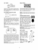
IGNITION SWITCH To start the engine, insert key into the ignition switch and turn clockwise to the START position. Release key to the ON position once engine has fired. See Figure 4. Refer to STARTING THE ENGINE in the OPERATION section of this manual for detailed starting instructions. The ignition switch is also used to operate the headlights.
LIFT LEVER BRAKE PEDAL BRAKE _ , //% IIII llnnnnq The lift lever is used to change the operating position (height) of the cutting deck. To operate, move the lever to the left, then place in the notch best suited for your application. The brake pedal is located on the right front side of the tractor above the drive pedal along the running board. The brake pedal can be used for sudden stops or for setting the parking brake.
SECTION 8: OPERATION SAFETY INTERLOCK SWITCHES SETTING This tractor is equipped with a safety interlock system for the protection of the operator. If the interlock system should ever malfunction, do not operate the tractor. Contact an authorized dealer in your area. The safety interlock system prevents the engine from cranking or starting unless the brake pedal is fully depressed, and the PTO lever is in the disengaged (OFF) position.
NOTE: DRIVING Do NOT leave the choke control out while operating the tractor. Doing so will result in a "rich" fuel mixture and cause the engine to run poorly. STOPPING Refer to the SLOPE GAUGE on page 6 to help determine slopes where you may not operate safely. WARNING: THE ENGINE • Place the PTO lever in the disengaged position ,_ (OFF) • Move the throttle control into the SLOW (turtle) position and allow the engine to "idle down" for ten seconds.
USING THE LIFT LEVER WARNING: To raise the cutting deck, move the lift lever to the left, then place it in the notch best suited for your application. Refer to SETTING THE CUTTING HEIGHT earlier in this section. TO avoid possible injury, do not allow anyone in the area of the tractor while mowing. Even if the area to be mowed has been cleared of foreign objects, small objects may be picked up and discharged by the mower.
• Determine the approximate distance necessary for proper adjustment and proceed, if necessary, to the next step. • Locate the two lock nuts on the opposite side of the stabilizer bracket. See Figure 7A. Tighten the lock nuts to raise the front of the deck; loosen the lock nuts to lower the front of the deck. • Loosen the two jam nuts on the rear side of the deck stabilizer bracket. See Figure 7A. • Retighten the two jam nuts loosened when proper adjustment is achieved.
BRAKE ADJUSTMENT Pivot Bar Hex Nut and Lock Washer If the tractor does not come to a complete stop when the brake pedal is completely depressed, or if the tractor's rear wheels can roll with the parking brake applied, the brake is in need of adjustment. The brake disc can be found on the right side of the transmission in the rear of the tractor. Adjust if necessary as follows: Axle • Looking at the transmission from the right side of the tractor, locate the compression spring and brake disc.
CARBURETOR ADJUSTMENT NOTE: A dirty air cleaner will cause an engine to run rough. Be certain it is clean and properly attached before adjusting carburetor. Refer to separate engine manual packed with your unit for information regarding air cleaner maintenance. made to the engine the engine are is WARNING: if any while adjustments running (e.g. carburetor), disengage all clutches and blades. Keep clear of all moving parts. Be careful of heated surfaces and muffler.
CUTTING DECK REMOVAL immediately after the tractor. WARNING: Do operating NOT remove deck Allow the engine and other moving parts ample time to cool down. maintenance, the PTO lever into any the WARNING: move Before performing disengaged (OFF) position, engage the parking brake, turn the ignition key to the OFF position and remove the key from the switch to avoid accidental starting. Several attachments are available for your tractor.
CHANGING THE DECK BELT(S) All belts on your tractor are subject to wear and should be replaced if any signs of cracking, shredding rotting are present. or IMPORTANT: The V-belts found on your tractor are specially designed to engage and disengage safely. A substitute (non-OEM) V-belt can be dangerous by not disengaging completely. For a proper working machine, use factory approved belts.
Belt Guard (mounted on tractor) (mounted on tractor) _£! Deck belt (Bottom) Engine Pulley PTO Engagement Plate PTO belt (Top) PTO Idler Pulleys Right Hand Pulley (beneath belt guard) Left Hand Double Pulley Center Pulley NOTE: Lefthand belt cover not shown for clarity. 46-inch deck shown.
Lower Drive Belt NOTE: Proper removal of the lower drive belt requires the removal of several tractor components. Read through the following procedure prior to attempting it to determine if you feel you could successfully complete it. If you don't, see an authorized MTD service dealer to have the belt changed. IMPORTANT: Note the routing of the lower drive belt around both the pulleys and the belt keepers BEFORE performing the following steps.
The blades may be removed replacement as follows. Double-idler (_ "_'jJ Idler j,dj. Rod Front of Tractor NOTE: • Place a block of wood between the center deck housing baffle and the cutting blade to act as a stabilizer. See Figure 19. _.- • Use a 15/16" wrench to remove the hex flange nut that secures the blade to the spindle assembly. See Figure 19. View shown from above tractor.
It is extremelyimportantthat each cuttingblade IMPORTANT: If removing the battery for any edge be groundequallyto maintainproperblade reason, disconnect the NEGATIVE (Black) wire from balance.An unbalanced bladewiltcauseexcessive it's terminal first, followed by the POSITIVE (Red) vibrationwhenrotatingat highspeeds,may cause wire. When re-installing the battery, always connect damageto the tractorandresultin personalinjury.
SECTION Trouble Engine will not crank 12: TROUBLESHOOTING Possible Corrective Cause(s) Safety switch button not depressed. Battery installed incorrectly. Battery is dead or weak. Blown fuse Throttle or choke Engine cranks but not in starting will not start ,osition. No fuel to the carburetor. No spark to spark plug(s). Dirty aircleaner. Engine smokes GUIDE Excessive vibration Engine oil has been overfilled. Engine loses crankcase _'acuum. Bent blade or damaged pulley.
Models 607, 608 & 609 _14 j_8 15/16 11. _ 12_. 5 REF. NO. 1 2 3 4 5 6 7 8 9 10 11 12 13 14 15 16 PART NO. 625-0051 629-0944 629-0126 710-0599 712-3006 725-1426 725-1657A 725-1741 725-1742 725-1745 725-1744 725-1747 725-3007A 736-0329 629-0309 729-0357 725-1381 DESCRIPTION Bulb/Socket Headlight Assembly Wiring Harness w/o Ref. 14 Harness Adapter, #18 x 5 Self4apping Screw, 1/4-20 x .
GREEN OP_G£_BLAOK SEATSWITCH _5,173S ( ORA_E_E GREEN _ PTOSWITCH B&UE _ 72S1_57A t OR_qGE __ J ( j _ ¥B_LOW_CK ORA_G_Cb_4 PTOPTO+ i KE"SVVITCH A,_O +12V YELLOW _ITE Ot \ F3 0"1 __ ORANGE REOt_CX OR_.
Models 607 & 608 L I i 26 -.
Tractor Body RER NO. 1 2 3 4 5 6 7 8 9 10 11 12 13 14 15 16 17 18 19 20 21 22 23 24 25 26 27 28 PART NO. 683-0195 710-0528 710-0599 710-0751 710-0895 710-0896 710-0924 712-0271 712-0292 712-0431 726-0211 726-0293 731-1854 731-2300 731-2301 731-2302 731-2303 731-2306 735-0126 736-0105 783-0475 783-0476A 783-0477 783-1034 783-1038 710-0106 710-0604A 710-1017 710-1238 710-3217 712-0142 RER NO. 29 30 31 32 33 34 35 36 37 38 DESCRIPTION Bracket Assembly Hex Cap Screw, 5/16-18 x 1.
Model 609 < > A, J o J 28
Tractor Body RER NO. 1 2 3 4 5 6 7 8 9 10 11 12 13 14 15 16 17 18 19 20 21 22 23 24 25 26 27 28 29 30 31 32 33 lUnits with B&S Single-cylinder SUnits with B&S Single-cylinder PART NO.
Models 607, 608 & 609 43 3 6 < > 8 5 1 15 26 30
Lift Assembly REP. NO. 1 2 3 4 5 6 7 8 9 10 11 12 13 PART NO.
Models 607, 608 & 609 24 32 27 25 37 33 29 32
Steering Assembly RER NO. 1 2 3 4 5 6 7 8 9 10 11 12 13 14 15 16 17 18 19 20 21 22 23 24 25 26 27 PART NO. 683-0304 710-0604A 783-0726A 783-0727 783-0728 710-0514 711-1409A 711-1408 712-0240 712-0241 712-0431 712-0459 712-3004A 717-1550A 717-1554 723-0448A 736-0169 736-3084 738-1001A 741-0475 741-0656 738-0372 631-0027 731-1687 731-0220 731-1459A 638-0019 638-0021 638-0020 638-0022 683-0128A REF. PART NO. NO.
Models 607, 608 & 609 • i i 29 79 58 • _.'- "/13 "35 65 58 56 /71 11-. 18\ 36\ 64 61" F 5 69 AO 62 / 64 23 76 _ 13 / 52 21 > 80 34
Drive System RER NO. 1 2 3 4 5 6 7 8 9 10 11 12 13 14 15 16 17 18 19 20 21 22 23 24 25 26 27 28 29 30 31 PART NO.
Models 607, 608 & 609 @ 20 12c 38. 39 \8 .
Single-speed Transmission RER NO. 1 2 3 4 5 6 7 8 9 10 11 12a 12b 12c 13 14 15 16 17 18 19 20 21 22 23 24 25 26 27 28 29 30 31 32 33 34 35 36 37 38 39 40 41 PART NO.
Models 607, 608 & 609 j3 57. j4 /-13 _53 f1_-14 - _54 15 z55 sj _17 12 f 6/_ "_" "_. 5 j 444 j 43 J z 56 9_ 16 _ 26 / v J z28 _g 2O Hook spring, Ref.
Power Take-off System REF. NO. 1 2 3 4 5 6 7 8 9 10 11 12 13 14 15 16 17 18 19 20 21 22 23 24 25 26 27 28 29 30 PART NO. 712-0431 732-0996 783-0733 732-0997 710-0604A 710-0751 712-0271 712-3044 725-1706 738-1014 738-1020 736-0407 723-0444 783-1031 725-1747 736-0222 725-1426 710-0599 712-0459 683-0304 736-3010 710-0831 736-0275 732-0944 736-0140 710-0642 736-0322 712-3004A 783-0653C 754-0485 754-0486 DESCRIPTION Flange Lock Nut, 3/8-16 Compression Spring, 1.31 x 3.0 Spacer Cup, 1.50D Compression Spring, .
Models 607, 608 & 609 ,9_''' "'_ 46-inch Deck 16 _See 49. PTO breakdown _ _55 "_ 64 65 7O 77 23 29 30 58 42-inch Deck 26. ® 2 38.
Cutting REP. NO. 1 2 3 4 5 6 7 8 9 10 11 12 13 14 15 16 17 18 19 20 21 22 23 24 25 26 27 28 29 30 31 32 33 34 35 36 37 38 39 40 41 42 43 PART NO.
Models 607, 608 & 609 _......
Engine Accessories Briggs & Stratton Opposed Twin O 19 41 face forward) 1 RED NO. 1 2 3 4 5 6 7 8 9 10 11 12 13 14 15 16 17 18 19 20 21 22 PART NO. 710-0148 710-0599 710-0604A 710-1237 710-1314 710-1315 712-3017 721-0460 726-0205 736-0119 736-0300 751B221535 751-0535 751-0564 751-0616 751-0650 751-0651 751-3140 751-3141 751-3142 783-0615 783-0625B REF. NO. 23 24 25 26 27 28 29 30 31 32 33 34 DESCRIPTION Self-tapping Screw, #8-32 x .375 Self-tapping Screw, 1/4-20 x .5 Self-tapping Screw, 5/16-18 x .
MANUFACTURER'S LIMITED WARRANTY FOR: YARD The limited warranty set forth below is given by MTD PRODUCTS INC ("MTD") with respect to new merchandise purchased and used in the United States, its possessions and territories. MTD warrants this product against defects in material and workmanship for a period of two (2) years commencing on the date of original purchase and will, at its option, repair or replace, free of charge, any part found to be defective in material or workmanship.