Electrofusion Installation Procedure Manual It is important to read and understand all instructions before attempting a fusion. Permanent field installations should be done only by operators who have been properly trained and certified as qualified. Should you have any questions or need installation training, please contact Central Plastics Company at 1-800-654-3872 or Your Local Central Plastics Representative.
Table of Contents Before You Start 1 Electrofusion Power Requirements 2 Proper Pipe Preparation for Electrofusion 3 Acceptable Markers for Electrofusion 4 Pipe Re-Rounding Statement 5 Fitting Restraint Statement 7 Barcode Scanning Instructions 8 Electrofusion Cooling Statement 9 Re-Fusion of Electrofusion Fittings Recommendation 10 Hydrostatic Testing of Electrofusion Fittings 11 Electrofusion Joining Procedures for Couplings 12 Electrofusion Joining Procedures for Sidewall/Saddle Fit
Before You Start The following is an installation guide for the purpose of assisting the installer in adequately preparing an electrofusion fitting and pipe for fusion. This document is a guide only, and should not be used in place of training by an authorized electrofusion instructor. The recommended joining procedures for the Central Electrofusion System detailed in this manual have been qualified in accordance with D.O.T. 192.
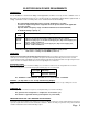
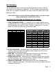
ELECTROFUSION POWER REQUIREMENTS GENERATORS For the installation of electrofusion fittings in field applications, it will be necessary to have a reliable source of AC power for the Electrofusion Processor to work properly in supplying the fitting with the right amount of energy.
Proper Pipe Preparation for Electrofusion Fittings For a pipe surface to be properly prepared for electrofusion the outer layer or “skin” of the pipe should be removed to expose a clean, virgin pipe material. This can be achieved by using one of several types of approved scraping tools. “Approved” scraping tools can vary widely between electrofusion manufacturers and they may not necessarily be a tool that is manufactured by the fitting manufacturer.
Markers Marks can be made on the outer surface of the pipe as a visual aid to help indicate the required scraper coverage. Marks made on the pipe should not be made with a “grease pencil” or other type of petroleum based marker that will leave a contaminate behind. Central Plastics Company’s only requirement for markers used on PE pipe during electrofusion preparation is that the marker be non-petroleum based.
Re-Rounding The non-brittle and flexible material characteristic of polyethylene makes it ideal for many pressure and non-pressure applications. But this material characteristic alone brings with it an important consideration that must be taken into account when using polyethylene pipe. “Care must be taken to ensure that the polyethylene pipe is not out-of-round before attempting the electrofusion process.” HOW DOES POLYETHYLENE PIPE BECOME OUT- OF- ROUND? 1.
WHY IS IT IMPORTANT TO ADDRESS THE OUT-OF-ROUND ISSUE FOR ELECTROFUSION INSTALLATIONS? One of the most critical functions of the electrofusion process is to close the gap between the pipe and the fitting and to build up interfacial pressures for the fusion process to take place. If this gap is not closed and the interfacial pressures cannot be built up, there is no way for the electrofusion joint to effectively achieve the high level of fusion integrity for which it was designed.
FITTING RESTRAINT ELECTROFUSION COUPLINGS Important Note: All Electrofusion Couplings (regardless of manufacturer) require the pipe to be restrained or sufficiently supported on each side of the pipe to; a) restrict movement during the fusion and cooling process, and b) alleviate or eliminate sources of stress and/or strain until both the fusion cycle and the cooling cycle are completed.
Note: Barcode Scanning Instructions Be sure the processor is ready and the display is reading “Read Data”. It is critical that the tip of the barcode reader be touching the barcode label. While holding the reader at a 15 to 30 degree angle start the scan beginning in the white area on one side of the label and move the reader evenly across the barcode into the white area on the opposite side. Move the reader in a smooth quick motion, without stopping, all the way across the label.
Electrofusion Fitting Cooling One of the most misunderstood and often ignored components of the entire electrofusion process is the cooling phase. It is often assumed that if the fitting is cool enough to touch it must be cool enough to remove the restraint device or even pressure test the connections. The cooling phase is critical to the success of the electrofusion process and careful attention should be given to insure that the stated cooling times are properly adhered to.
Re-Fusion of Electrofusion Fittings Central Plastics electrofusion fittings can be re-fused only in the event of an input power interruption, i.e. fusion leads were detached during fusion, generator runs out of gas, processor malfunction, or other circumstance that results in processor input power interruption. The recommended procedure for re-fusing fittings is: Fitting should remain in clamped position and be allowed to cool to ambient temperature.
Page 11
Electrofusion Joining Procedures for Couplings 1.) Clean the pipe ends, or the area to be fused, by removing dirt, mud, and other debris from pipe ends. Clean water can be used for initial cleaning of pipe surfaces prior to scraping and isopropyl alcohol is recommended after scraping. 2.) Check pipe for out-of-round condition. If fusion area is found to be out-of-round, take appropriate steps to bring fusion area back within required tolerances. 3.
5.) Check the pipe surface for any embedded debris that may cause damage to scraping tools, and once more make sure that the outer pipe surface is clean and free of any dirt or mud that could recontaminate the scraped pipe surfaces. 6.) Scrape the outside of the pipe surface to remove oxidation and other contaminates. Use an appropriate scraping tool as recommended by Central Plastics.
8.) Place the fitting on the area to be fused and restrain using an approved restraint device .(See “Restraint” page 7) Use rubber mallet (or metal hammer and wood blocks) to move coupler onto pipe, if necessary. Ensure that stab depth marks are properly located and visible. 9.) Attach processor leads to the fitting and proceed with fusion as described for standard joining. (If using a Bar-Code Processor see “Scanning Instructions” page 8) 10.
Electrofusion Joining Procedures for Sidewall/Saddle Fittings (for use with under-clamp on 1-1/4” - 6” fitting bases) 1.) Identify the location of the fitting to be installed on the pipe and mark the area with a non-greasy marker. 2.) Check the pipe surface for any embedded debris that may cause damage to scraping tools making sure that the outer pipe surface is clean and free of any dirt or mud that could recontaminate the scraped pipe surfaces. 3.
5.) Remove the fitting from the bag and place it on the area to be fused 6.) Without moving the fitting, slide the Under-Clamp onto the base of the fitting. 7.) Make sure the fitting is centered in the Under-Clamp and then pivot the handle into the secured position. 8.) Attach processor leads to the fitting and proceed with fusion as described for standard joining.
Electrofusion Joining Procedures for Sidewall /Saddle Fittings (for use with Top-Load Clamp on 8”, 10” & 12” fitting bases) 1) Equipment Needed: 1. 2. 3. 4. 5. 6. 7. Top Load Clamp Top Load Clamp Fitting Adapters Electrofusion Processor Sure-Form Scraper 8”, 10” or 12” Electrofusion Saddle Fitting Permanent Marker Re-Rounding Clamps (if necessary) 2) Place fitting on pipe and mark area to be scraped.
Electrofusion Joining Procedures for Branch Saddle Fittings (for use with T-Clamp ) 1.) Clean the area to be fused by removing dirt, mud, and other debris from pipe ends (pay close attention to the drill mud residue in trenchless applications). Clean water can be used for initial cleaning prior to scraping and isopropyl alcohol is recommended after scraping if necessary. 2.) Check the pipe for out-of-round condition.
5.) Use your marks to make sure the alignment of the fitting is correct. CAUTION: Fusion zone cannot be located over the hole. Correct Alignment Incorrect Alignment 6.) Check the pipe surface for any embedded debris that may cause damage to scraping tools making sure that the outer pipe surface is clean and free of any dirt or mud that could recontaminate the scraped pipe surfaces. 7.) Scrape the area to be fused with an approved scraping tool.
9.) Place the fitting on the area to be fused and restrain using the T-Clamp. 10.) Insert the T-Clamp through the top of the Branch Saddle and into entrance hole. 11.) Tighten T-Clamp down until it is snug on the pipe surface then turn handle 1/4 turn more.
12.) Check to make sure there is no excessive gap between the pipe and the fitting. Use a .015” feeler gauge to check interface gap 13.) Attach processor leads to the fitting and proceed with fusion as described for standard joining. (If using a Bar-Code Processor see “Scanning Instructions” page 8) 14.) Disconnect and remove the processor leads when the fusion cycle has been completed. 15.
Electrofusion Joining Procedures for Flex Restraints (for use with Ratchet Strap Clamp ) (1) Identify the desired location for the Flex Restraints (2) Pipe must be clean. Remove all sources of contamination. A minimum 70% concentration of Isopropyl Alcohol and a lint free rag should be used to clean the surface area to be fused. (3) For the purpose of insuring a good scrape of the fusion area, use an appropriate marker to randomly mark over the outlined fusion area.
(6) Tighten the strap until the restraints are conformed to the pipe wall. Make sure the Flex Restraint makes contact with the pipe over the entire fusion area. If more than one restraint is to be used, make sure that all fittings are in place before fully tightening the ratchet straps. NOTE: If multiple restraints are to be used, it is helpful to place the fitting over the scraped area and to secure it in place with masking tape or duct tape until the strap can be applied.
Examples of Incorrect Electrofusion Joints The most common cause of joint failure for an electrofusion fitting falls into a category of failure classified as improper pipe preparation . Most issues associated with improper pipe preparation can be controlled by the installer and with adherence to proper installation techniques. Improper pipe preparation is avoidable .
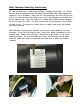
Examples of Incorrect Electrofusion Joints PIPE UNDER-SCRAPED The visible tool marks show that some effort was made to scrape the pipe. Unfortunately there was not enough material removed to allow a proper fusion. While most of the fitting did not fuse to the pipe, a small section did. When the joint failed, the stress on the section that did fuse was too great, causing the coupling to break.
Examples of Incorrect Electrofusion Joints EXCESS GAP When the gap between the pipe and fitting is excessive the expansion of molten polyethylene cannot completely fill the space for a successful fusion. This can be caused by undersized pipe, over scraping, or severely out of round pipe. SHORT-STAB / BINDING A short-stab is the result of not centering the pipe ends in the fitting. Binding is caused by a severe mis-alignment or excessive lateral forces on the joint.
DESTRUCTIVE TESTING PROCEDURES FOR ELECTROFUSION FITTING QUALIFICATION The following test methods are useful as an evaluation of bonding strength and quality between the pipe and fitting. Similar tests can be used as user qualification criteria. As these methods are destructive, they are only useful in determining joint quality of a fusion to verify that proper procedures were followed.
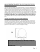
Figure 1 Figure 2 1. TAPPING TEES Tapping tees should be left intact for crush testing. Pipe lengths can be cut to the edges of the fitting base. Place the pipe and fitting into a vise so that the jaws are within 1/2" (13mm) of the bottom of the saddle, ( Figure 3). Close the vise until the pipe walls meet, ( Figure 4). Inspect the crushed specimens for separation of the pipe and fitting in the fusion zone.
Further evaluations are possible by cutting the fusion area and surrounding pipe and fitting materials in thin strips for bend tests. The strips are then placed into a vise and bent directly on the fusion interface and evaluated for separation. The same visual criteria are used for fusion evaluation tests as is used for crush tests. Couplings should have four strips cut from the fusion interface at 90° intervals as shown in figure 5. The strips should be approximately 1/16"(1.