Operator's Manual Transmatic Lawn Tractors Model Series 660 thru 679 IMPORTANT: Read safety rules and instructions carefully before operating equipment. Warning: This unit is equipped with an internal combustion engine and should not be used on or near any unimproved forestcovered, brush-covered or grass-covered land unless the engine's exhaust system is equipped with a _,park arrester meeting applicable local or state laws (if any).
TABLEOFCONTENTS Content Page Important Safe Operation Practices ................................................................... 3 thru 6 Slope Gauge ...................................................................................................... 7 Assembling your Lawn Tractor .......................................................................... 8 Know Your Lawn Tractor ....................................................................................
SECTION 1: IMPORTANTSAFEOPERATION PRACTICES WARNING: This symbol points out important safety instructions which, if not followed, could endanger the personal safety and!or property of yourself and others. Read and follow all instructions in this manual before attempting to operate this machine. Failure to comply with these instructions may result in personal injury, When you see this symbol--heed its warning.
23. Mufflerandenginebecomehotandcancausea bum.Donottouch. 3. 24. Checkoverhead clearances carefullybeforedriving underlowhangingtreebranches, wires,door openingsetc., where the operator may be struck or pulled from the unit, which could result in serious injury. 4. 25. Disengage all attachment clutches, depress the brake pedal completely and shift into neutral before attempting to start engine. 5. 26. Your machine is designed to cut normal residential grass of a height no more than 10".
c, Before and while backing, look behind and down for small children. d. Never carry children, even with the blade(s) shut off, They may fall off and be seriously injured or interfere with safe machine operation. e. Use extreme care when approaching blind corners, doorways, shrubs, trees or other objects that may block your vision of a child who may run into the machine. f, Disengage the cutting blade(s) before shifting in reverse.
Replace the blade(s) with the original equipment manufacturer's (O.E.M.) blade(s) only, listed in this manual. "Use of parts which do not meet the original equipment specifications may lead to improper performance and compromise safety!" 6. Mower blades are sharp. Wrap the blade or wear gloves, and use extra caution when servicing them. 7. Keep all nuts, bolts, and screws tight to be sure the equipment is in safe working condition. 8. Never tamper with the safety interlock system or other safety devices.
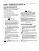
SIGHT AND HOLD THIS LEVEL WITH A VERTICAL TREE 14 A POWER POLE I A CORNER OF A BUILDING OR A FENCE POST . .. 8, & 0 I _i WARNING Do not mow on inclines with a slope in excess of 15 degrees (a rise of approximately 2-1/2 feet every 10 feet). A riding mower could overturn and cause serious injury. If operating a walk-behind mower on such a slope, it is extremely difficult to maintain your footing and you could slip, resulting in serious injury.
SECTION1: ASSEMBLING YOURLAWNTRACTOR /IMPORTANT: After assembly, service engine with gasoline, and check oil level as instructed in the separate engine manual packed with your unit. NOTE: Reference to right or left hand side of the unit is observed from the driver's seat, facing forward. Tools RequiredFor Assembly (1) 1/2" wrench or socket wrench* ,_ DANGER (1) 9/16" wrench or socket wrench IBattery contains sulfuric acid. Refer to warning (2) 7/16" wrenches or socket wrenches at right.
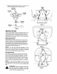
Placethesteeringwheelcapoverthecenterofthe steeringwheelandseatitwithyourhand. Screws Steering Hex Lock Wheel_ap _ Cupped __ Steering Bellow Manual Adjustment Seat Figure 2 g Shaft Figure 1 Seat Pivot AttachingTheSeat There are two different seat pivot brackets used on this series of lawn tractor, a manual adjustment seat or a quick adjustment seat. See Figure 2 and 3 to identify which seat is on your unit. Follow the instructions which apply to your lawn tractor.
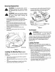
RemovingShippingBrace WARNING: The shipping brace, used for packaging purposes only, must be removed and discarded before operating your riding mower. Line up the bolt on the mulching plug with the hole in the top of the deck. Push up on the end of the mulching plug and secure with the wing nut. Chute Deflector Wing Nut engine is off, remove the ignition key,mower's and set WARNING: Make sure the riding the parking brake before removing the shipping brace.
• When deck is level, secure end of adjustable lift link with flat washer and hairpin clip. * Deck Hanger =_Channel _. Remove the hex bot and nut from the negative (black) cable. Attach negative cable to the negative terminal with this bolt and nut.
ChokeControl Clutch-brakePedal The choke control is located on the left side of the dashboard and is operated manually. Details for the choke operation are covered in the separate engine manual packed with your unit. See Figure 9, The clutch-brake pedal is located on the left side of the lawn tractor. Depressing the clutch-brake pedal part way disengages the clutch. Pressing the pedal all the way down disengages the clutch and engages the disc brake. See Figure 9. Light Switch (.
Deck Lift Indicator(If Equipped) If so equipped, the deck lift indicator marks the position being used for the lift lever. Select the lift lever position desired, press the indicator lever outward, move it to the position immediately below the lift lever and release the indicator lever. See Figure 11. Lift Lever SettingThe CuttingHeight • • Select the position for the lift Iever which gives the desired cutting height.
When stopping the unit to empty a grass bag, etc., follow the instructions above. This procedure will also eliminate "browning" the grass, which is caused by hot exhaust gases from a running engine. StoppingTheEngine Turn the ignition key to the left to the OFF position. Remove the key to prevent accidental starting. WARNING: If you strike a foreign object, stop the engine, disconnect the spark plug wire(s) and ground against the engine. Thorougly inspect the machine for any damage.
SECTION4: MAKINGADJUSTMENTS CarburetorAdjustments adjustments while engine to ismake running, WARNING: Nevertheattempt any except where specified in the operator's manual, _ WARNING:; If any adjustments need to be made to the engine while the engine is running (e.g. carburetor), disengage PTO, shift into neutral and set the parking brake. Keep clear of all moving parts. Be careful of muffler, engine and other surrounding heated surfaces.
Stabilizer Shaft Assembly Disengagement Slot Fiat Washer Hairpin Clip i38" IDecksl Disengagement Stabilizer Shaft Assembly Loosen Hex Bolt /Rod Figure 14 BrakeAdjustment Spimg ;er Flat Washer Hairpin Clip The brake is located by the right rear wheel inside the frame. During normal operation of this machine, the brake is subject to wear and will require periodic examination and adjustmenLSee Figure 15, ,ote WARNING: Never attempt to adjust the brake while the engine is running.
....._Speed Control Lever Variable Speed Assembly StopRod Back Hairpin Clip and Flat Washer Brake Rod Figure 16 Release the clutch-br_ke pedal completely, then slowly depress the pedal al! the way (to park position). Hold the pedal in this position. Turn the engine off. After engine stops cornpletely, release the clutchbrake pedal. Place speed control lever in second position, Remove the cotter pin and flat washer which secures the speed control tink to the variable speed torque bracket assembly.
• • • Remove the hex nut and lock washer, and drop the end of the tie rod from the axle bracket. See Figure 17. A 4 Loosen the hex jam nut on tie rod. Adjust the tie rod assembly for correct toe-in. Tie Rod \ _ t, Front _ _..== ° .I (1116" - 5/16" Less Than A) Figure 18 Hex Jam Nut CarburetorAdjustments Tie Rod End Hex Nut Lock Washer WARNING; If any adjustments are made to the engine while the engine is running (e.g. carburetor), disengage all clutches and blades.
Wheels BallJoints The front wheels may be provided with optional grease fittings. The rear wheels must be removed from the axle Forlubrication. Lubricate at ]east once a season with automotive multi-purpose grease. The ball joints and drag link ends are permanently lubricated. PivotPoints Lubricate all pivot points with light oil at least once a season.
• • 12" Drain Ho__ Drain Valve Figure 21 Remove the hex flange nut which holds the blade to the blade spindle. Remove the blade from the spindle. Sharpening Remove the cutting blades by following the directions of the preceding section. When sharpening the blades, follow the original angle of grind as a guide, it is extremely important that each cutting edge receives an equal amount of grinding to prevent an unbalanced blade.
To charge the battery: Battery P!N 725-1705D-Charge at 2-3 amps for one hour. Battery PiN 725: 1707D, 725-0453G, and 725-1750_Charge at 6 amps for one hour.
Removethebeltguardsateachdeckpulleyby removing theself-tapping screws.SeeFigure23. Self-Tapping Screws / Stabilizer Plate Rear DriveBelt • Belt iuard • Place shift lever in neutral position. Unscrew the shift knob and the speed control knob (if located on the console). Remove the two truss head screws which secure the transmission cover. See Figure 24. Lift the transmission cover. Unplug the safety wire from beneath the transmission cover. See Figure 24. Remove transmission cover.
, NOTE: Removethebeltkeeperpinsfromtheenginepulley belt guard. Refer to Figure 22. NOTE: Make certain belt keeper reassembled as shown in Figure 22. pins When reassembling, make certain inside the belt keeper pin& See Figure 22. belt is are !\ Unhook the deck belt from the engine pulley. Remove the center bolt, lock washer and flat washer, and let the engine pulley drop down so the belt is past the belt guards.
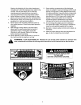
SECTION8: TROUBLE SHOOTING GUIDE Trouble Cause(s) Safety switch button not depressed, Battery installed incorrectly. Corrective Action There are two switches in the starting circuit of your Unit: the clutch pedal switch and the deck lift lever switch. Make certain the actUator is fully depressing the buttons on each switch. The battery must be installed with negative terminaI attached to black ground wire. Negative terminal is identified at the post by "NEG', "N" or ,,2.
SECTION 9: OPTIONAL EQUIPMENT At the time of manufacture of lawn tractor, the following optional equipment is available. NOTE: These lawn tractors are not designed ground-engaging equipment (tillers, plows, etc.). NOTE: *Available threugh your local dealer or from Agri-Fab Inc., 303 W. Raymond Street, Sullivan, Illinois 61951. for Model No.
NOTES 26
NOTES 27
MANUFACTURER'S The limited warranty set forth below LIMITED WARRANTY is given by MTD PRODUCTS INC ("MTD") with respect to new merchandise purchased and used in the United States, its possessions and territories. MTD warrants this product against defects in material and workmanship for a period of two (2) years commencing on the date of original purchase and will, at its option, repair or replace, free of charge, any part found to be defective in material or workmanship.