
Manual


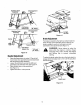


ChokeControl
The choke control is located on the left side of the
dashboard and is operated manually. Details for the
choke operation are covered in the separate engine
manual packed with your unit. See Figure 9,
LightSwitch (.Equipped)
The head lamps are operated by pushing the light
switch located on the dashboard. The head lamps will
only operate when the engine is running. See Figure 9.
Ammeter(ifEquipped)
The ammeter registers the rate of battery charge or
discharge. The ammeter will register on the discharging
side with starting the engine. It should register on the
opposite side (charging) when the engine is running in
the fast position until the battery is completely charged.
With a fully charged battery or with the engine idling,
the ammeter will not show a charge. See Figure 9.
Clutch-brakePedal
The clutch-brake pedal is located on the left side of the
lawn tractor. Depressing the clutch-brake pedal part
way disengages the clutch. Pressing the pedal all the
way down disengages the clutch and engages the disc
brake. See Figure 9.
NOTE: The clutch-brake pedal must be depressed to
start the engine.
ParkingBrake
The speed control lever is used to set the parking
brake. To set the parking brake, depress the clutch-
brake pedal. Move the speed control lever out of the
notches to the parking brake position. Release the
speed control lever and the clutch-brake pedal.
To release the parking brake, depress the clutch-brake
pedal and move the speed control lever out of the
notches to the desired position. Release the speed
control lever and the clutch-brake pedal.
ShiftLever
The shift lever is located in the center of the console
and has three positions, FORWARD, NEUTRAL and
REVERSE. See Figure 9. The clutch-brake pedal must
be depressed and the lawn tractor must not be moving
when shifting gears. Do not force the shift lever.
Release the clutch-brake pedal slightly to line up the
shifting collar in the transmission. Then try to shift
gears.
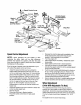
SpeedControlLever
The speed control lever is located either on the console
or on the right fender. See Figure 10. The speed control
lever allows you to regulate the ground speed of the
lawn tractor. To select the ground speed, depress
clutch pedal. Move speed control lever out of the
notches and backward to slow lawn tractor, forward to
increase speed. When desired speed has been
obtained, release lever in that position. Whenever
clutch is released, unit will automatically go to the pre-
set speed.
Speed
Control
Lever
Speed
Shift Control
Lever Lever
Figure 10
NOTE: The parking brake must be set if the operator
leaves the seat with the engine running
Interlocks(NotShown)
Interlock safety switches are located by the clutch-
brake pedal, the lift lever, the shift lever and under the
seat.
Before the engine will start, the clutch-brake pedal must
be depressed all the way and the lift lever must be in
the BLADES STOP position.
Before the unit can be shifted into reverse or if the
operator leaves the seat, the lift lever must be in the
BLADES STOP position.
IndicatorLights (.Equipped)
If your unit is equipped with indicator lights, two or three
indicator lights are located in the dash panel. If a light
illuminates when attempting to start the unit, proceed
as follows.
CLUTCH--Depress the clutch pedal.
PTO--PIace lift lever in the BLADES STOP position.
OIL (Vanguard Twin and Intek twin Engines Only)-
Check the crankcase oil level, and add oil as required,
CuttingControls
Lift Lever
The lift lever is used to raise and lower the cutting deck
and to engage and disengage the blades. Pulling it all
the way back and locking it disengages the blades.
NOTE: The lift lever must be in the BLADES STOP
position when starting the engine, when shifting into
reverse and if the operator leaves the seat. See Figure
11.
12