YARD Operator's Manual Transmatic Lawn Tractors Model Series 660 thru 679 IMPORTANT: Read safety rules and instructions carefully before operating equipment. Warning: This unit is equipped with an internal combustion engine and should not be used on or near any unimproved forest* covered, brush*covered or grass-covered land unless the engine's exhaust system is equipped with a spark arrester meeting applicable local or state laws (if any).
TABLEOFCONTENTS Content Page Important Safe Operation Practices ................................................................... 3 thru 6 Slope Gauge ...................................................................................................... 7 Assembling your Lawn Tractor .......................................................................... 8 Know Your Lawn Tractor ....................................................................................
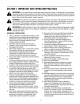
SECTION1: IMPORTANT SAFEOPERATION PRACTICES WARNING: This symbol points out important safety instructions which, if not followed, could endanger the personal safety and/or property of yourself and others. Read and follow all instructions in this manual before attempting to operate this machine. Failure to comply with these instructions may result in personal injury. When you see this symbol--heed its warning.
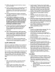
23. Mufflerandenginebecomehotandcancausea burn.Donottouch. 24. Checkoverhead clearances carefullybeforedriving underlowhangingtreebranches, wires,door openingsetc.,wheretheoperatormaybestruckor pulledfromtheunit,whichcouldresultinserious injury. 25. Disengage allattachment clutches,depressthe brakepedalcompletely andshiftintoneutralbefore attempting tostartengine. 26. Yourmachineis designedto cutnormal residentialgrassof a height no more than 10". Do not attempt to mow through unusually tall, dry grass (e.
g. c. Beforeandwhilebacking,lookbehindand downforsmallchildren. d. Nevercarrychildren,evenwiththeblade(s) shutoff.Theymayfalloffandbeseriously injuredorinterferewithsafemachine operation. e. Useextremecarewhenapproaching blind corners,doorways, shrubs,treesorother objectsthatmayblockyourvisionofa child whomayrunintothemachine. f. Disengage thecuttingblade(s)before shiftinginreverse.The"No-Cut-In Reverse" featureisa remindernottocutinreverseand to helpavoidbackoveraccidents. Donot defeatit. g.
Replacetheblade(s)withtheoriginalequipment manufacturer's (O.E.M.)blade(s)only,listedinthis manual."Useofpartswhichdonotmeetthe originalequipment specifications mayleadto improperperformance andcompromise safety!" 6. Mowerbladesaresharp.Wrapthebladeorwear gloves,anduseextracautionwhenservicingthem. 7. Keepallnuts,bolts,andscrewstighttobesurethe equipment is insafeworkingcondition. 8. Nevertamperwiththesafetyinterlocksystemor othersafetydevices.Checktheirproperoperation regularly. 9.
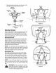
SIGHT AND HOLD THIS LEVEL WITH A VERTICAL TREE u91 A POWER POLE & O m _b WARNING Do not mow on inclines with a slope in excess of 15 degrees (a rise of approximately 2-1/2 feet every 10 feet). A dding mower could overturn and cause sedous injury. If operating a walk-behind mower on such a slope, it is extremely difficult to maintain your footing and you could slip, resulting in serious injury. Operate RIDING mowers up and down slopes, never across the face of slopes.
SECTION1: ASSEMBLING YOURLAWNTRACTOR IMPORTANT:After assembly, service engine with gasoline, and check oil level as instructed in the separate engine manual packed with your unit. NOTE: Reference to right or left hand side of the unit is observed from the driver's seat, facing forward.
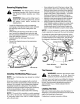
Place the steering wheel cap over the center of the steering wheel and seat it with your hand. Steering Screws Whee_ap Hex Lock _i_ Bolt _ Cupped _ Washer Steering Bellow Manual Adjustment Seat Figure 2 Steering Shaft Figure 1 Seat Pivot Bracket AttachingTheSeat @ There are two different seat pivot brackets used on this series of lawn tractor, a manual adjustment seat or a quick adjustment seat. See Figure 2 and 3 to identify which seat is on your unit.
Never attempt to mulch if the lawn is damp. Wet grass tends to stick to the underside of the cutting deck preventing proper mulching of the clippings. Do NOT attempt to mulch more than 1/3 the total height of the grass or approximately 1-1/2 inches. Doing so will cause the clippings to clump up beneath the deck and not be mulched effectively. Maintain a slow ground speed to allow the grass clippings more time to effectively be mulched.
Removethehairpinclipandflatwasherfromthe bottomoftheadjustable liftlinkontheleftsideof thedeck.(Hairpinclipandflatwasherareonthe insideoftheliftlink.) Pulltheadjustableliftlinkoutofthedeckhanger channel.SeeFigure7.Turntheadjustable liftlink upordownasnecessary tolevelthedeck.Usually onlyoneortwoturnsareneeded. Inserttheendoftheadjustable liftlinkintothehole inthedeckhangerchannel.Recheckthe adjustment. Readjustifnecessary. Whendeckislevel,secureendofadjustable liftlink withflatwasherandhairpinclip.
SpeedControlLever Light Switch The speed control lever is located either on the console or on the right fender. See Figure 10. The speed control lever allows you to regulate the ground speed of the lawn tractor. To select the ground speed, depress clutch pedal. Move speed control lever out of the notches and backward to slow lawn tractor, forward to increase speed. When desired speed has been obtained, release lever in that position.
Beforetheunitcanbeshiftedintoreverseorifthe operatorleavestheseat,theliftlevermustbeinthe BLADES STOPposition. DeckLift Indicator(If Equipped) If so equipped, the deck lift indicator marks the position being used for the lift lever. Select the lift lever position desired, press the indicator lever outward, move it to the position immediately below the lift lever and release the indicator lever. See Figure 11. IndicatorLights(.
Move throttle control to full throttle to prevent strain on the engine and to operate the cutting blades. Place the shift lever in either the FORWARD or REVERSE position. Release the parking brake by depressing the clutch-brake pedal, pressing outward on the speed control lever and moving to desired position. Use first speed position when operating the lawn tractor for the first time. Release clutch-brake pedal slowly to put unit into motion.
GrassCollectorAvailable Grass Collector Model OEM-190-063 NOTE: Under normal usage bag material is subject to wear, and should be checked periodically. Be sure to use only factory authorized replacement bag. is available as optional equipment for lawn tractors with 38" and 42" decks. Grass Collector Model OEM-190-103 is available for lawn tractors with 46" decks. WARNING: Do not operate the cutting deck unless the discharge cover or entire grass catcher are in the proper operating position.
Check the adjustment by placing the lift lever in the BLADES STOP position. The deck should move up and forward, allowing the belt to become loose. Start and test for disengagement. Repeat procedure as necessary. Slot Shift Stabilizer Shaft Assembly Disengagement Loosen Hex Bolt Figure 14 Hairpin Clip Stabilizer Shaft Assembly [38" Decks I BrakeAdjustment Disengagement Rod The brake is located by the right rear wheel inside the frame.
Variable Speed ue Bracket Assembly Stop_od Back of Hairpin Clip and _: Flat Washer Brak= Rod Figure 16 Release the clutch-brake pedal completely, then slowly depress the pedal all the way (to park position). Hold the pedal in this position. Turn the engine off. After engine stops completely, release the clutchbrake pedal. Place speed control lever in second position. Remove the cotter pin and flat washer which secures the speed control link to the variable speed torque bracket assembly.
Remove the hex nut and lock washer, and drop the end of the tie rod from the axle bracket. See Figure 17. Loosen the hex jam nut on tie rod. Adjust the tie rod assembly for correct toe-in. _1 A Tie Rod \ Front I [ B "J (1/16" - 5/16" Less Than A) Figure 18 Hex Jam Nut CarburetorAdjustments Tie Rod End WARNING: If any adjustments are made to the engine while the engine is running (e.g. carburetor), disengage all clutches and blades. Keep clear of all moving parts.
Wheels BallJoints The front wheels may be provided with optional grease fittings. The rear wheels must be removed from the axle for lubrication. Lubricate at least once a season with The ball joints and drag link ends are permanently lubricated. automotive multi-purpose grease. PivotPoints Lubricate all pivot points with light oil at least once a season.
Remove the hex flange nut which holds the blade to the blade spindle. Remove the blade from the spindle. Sharpening Remove the cutting blades by following the directions of the preceding section. When sharpening the blades, follow the original angle of grind as a guide. It is extremely important that each cutting edge receives an equal amount of grinding to prevent an unbalanced blade.
To charge the battery: Battery P!N 725-1705D-Charge at 2-3 amps for one hour. Battery P!N 7251707D, 725-0453G, and 725-1750--Charge at 6 amps for one hour.
Remove the belt guards at each deck pulley by removing the self-tapping screws. See Figure 23. Self-Tapping Stabilizer Plate Rear Drive Belt Place shift lever in neutral position. Unscrew the shift knob and the speed control knob (if located on the console). Remove the two truss head screws which secure the transmission cover. See Figure 24. Belt _uard Lift the transmission cover. Unplug the safety wire from beneath the transmission cover. See Figure 24. Remove transmission cover.
Removethebeltkeeperpinsfromtheenginepulley NOTE: When reassembling, make certain belt is inside the belt keeperpins. See Figure 22. belt guard. Refer to Figure 22. NOTE: Make certain belt keeper reassembled as shown in Figure 22. pins are Unhook the deck belt from the engine pulley. Remove the center bolt, lock washer and flat washer, and let the engine pulley drop down so the belt is past the belt guards. t/Va_ble Speed Pulley Center Bolt Lock Washer Flat Washer Pins , Figure 26 .
SECTION8: TROUBLE SHOOTING GUIDE Trouble Possible Corrective Action Cause(s) Engine will not crank Safety switch button not depressed. Battery installed incorrectly. Battery is dead or weak. Blown fuse or circuit breaker. Engine ground wire loose. Throttle or choke Engine cranks but not in starting will not start 3osition. No fuel to the carburetor. No spark to spark plug. Dirty air cleaner.
SECTION 9: OPTIONAL EQUIPMENT At the time of manufacture of lawn tractor, the following optional equipment is available. NOTE: These lawn tractors are not designed ground-engaging equipment (tillers, plows, etc.). NOTE: *Available through your local dealer or from Agri-Fab Inc., 303 W. Raymond Street, Sullivan, Illinois 61951. for Model No.
NOTES 26
NOTES 27
MANUFACTURER'S LIMITED WARRANTY FOR: YARD The limited warranty set forth below is given by MTD PRODUCTS INC ("MTD") with respect to new merchandise purchased and used in the United States, its possessions and territories. MTD warrants this product against defects in material and workmanship for a period of two (2) years commencing on the date of original purchase and will, at its option, repair or replace, free of charge, any part found to be defective in material or workmanship.