
Manual


Back
of
Hairpin
Clip and _:
Flat Washer
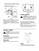
Variable Speed
ue Bracket
Assembly
Stop_od
Brak=
Rod
Figure 16
SpeedControlAdjustment
NOTE: When operating the unit initially or after
replacing the belts, there will be little difference
between the highest two speeds until after the belts
have gone through a break-in period and have seated
themselves into the pulleys.
If the full range of speeds cannot be obtained on your
unit, adjust the speed control as follows.
Adjust the speed control lever by pushing the
clutch-brake pedal forward until it hits the stop rod
on the running board. See Figure 16. Have another
person hold the pedal in this position as you make
the following adjustment. Place the speed control
lever in parking brake position. Remove the hairpin
clip and flat washer, and adjust the ferrule on the
rod so it is against the back end of the slot. See
Figure 16. Then lengthen rod one more turn.
Reassemble and secure with the flat washer and
hairpin clip.
Adjust the speed control link as follows to obtain the
correct neutral adjustment.
Start the engine.
Place the shift lever in Neutral position.
Place the speed control lever in high speed
position.
Release the clutch-brake pedal completely, then
slowly depress the pedal all the way (to park
position). Hold the pedal in this position.
Turn the engine off.
After engine stops completely, release the clutch-
brake pedal.
Place speed control lever in second position.
Remove the cotter pin and flat washer which
secures the speed control link to the variable speed
torque bracket assembly.
Push the clutch-brake pedal backward by hand as
far as itwill go using light pressure. Hold it in this
position as you thread the speed control link in or
out of the ferrule until it lines up with the pin on the
variable speed torque bracket assembly.
Secure speed control link to variable speed torque
bracket assembly with flat washer and cotter pin.
WheelAdjustment
(UnitsWithAdjustableTie Rod)
The caster (forward slant of the king pin) and the
camber (tilt of the wheels out at the top) require no
adjustment. Automotive steering principles have been
used to determine the caster and camber on the tractor.
The front wheels should toe-in between 1/16 - 5/16
inch.
To adjust the toe-in, follow these steps.
17