OPERATOR'S MANUAL Transmatic Garden Tractor Models 820 Thru 829 840 Thru 849 IMPORTANT: Read safety rules and instructions carefully before operating equipment. Warning: This unit is equipped with an internal combustion engine and should not be used on or near any unimproved forestcovered, brush-covered or grass-covered land unless the engine's exhaust system is equipped with a spark arrester meeting applicable local or state laws (if any).
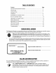
TABLEOFCONTENTS Content Page Important Safe Operation Practices ................................................................... 3 Slope Gauge ...................................................................................................... 6 Hardware Pack .................................................................................................. 7 Unpacking ..........................................................................................................
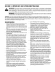
SECTION1: IMPORTANT SAFEOPERATION PRACTICES WARNING: This symbol points out important safety instructions which, if not followed, could endanger the personal safety and/or property of yourself and others, read and follow all instructions in this manual before attempting to operate your lawn mower, failure to comply with these instructions may result in personal injury. When you see this symbol, heed its warning.
SlopeOperation Children Slopes are a major factor related to loss of control and tip-over accidents which can result in severe injury or death. All slopes require extra caution. If you cannot back up the slope or if you feet uneasy on it, do not mow it. Tragic accidents can occur if the operator is not alert to the presence of children. Children are often attracted to the machine and the mowing activity. Never assume that children will remain where you last saw them.
• • • • • • • • Wedonotrecommend theuseofpressure washersorgardenhosetocleanyourunit.They maycausedamagetoelectriccomponents, spindles,pulleys,bearingsortheengine.Theuse ofwaterwillresultinshortenedlifeandreduce serviceability. Checkthebladeandenginemountingboltsat frequentintervalsforpropertightness.Also, visuallyinspectbladefordamage(e.g.,excessive wear,bent,cracked).Replacewithbladewhich meetsoriginalequipment specifications.
USE THIS PAGE AS A GUIDE TO DETERMINE SLOPES WHERE YOU MAY NOT OPERATE SAFELY. SIGHT AND HOLD THIS LEVEL WITH A VERTICAL TREE A POWER POLE A CORNER OF A BUILDING OR A FENCE POST I I t.O m Z m I.M Do not mow on inclines with a slope in excess of 15 degrees (a rise could overturn and cause serious injury. If operating a walk-behind your footing and you could slip, resulting in serious injury.
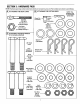
SECTION3: HARDWARE PACK NOTE: A Hardware pack may contain extra items which are not used on your unit. Part numbers are shown in parentheses. IATTACHING _[O_1]... THE DECK LINKS _..[{1(|{|(I fU(ifl{l(ll[llTll) al ATTACHING THE CUTTING DECK hardware may be assembled to the deck €=_ Sma,, __ Clevis Pin -_p] I Hairpin NOTE: This " (711-0701) I _, J clip Eyebotts (711-0817) (Not Shown to _L_BJ (714-0104) Flat Washers 1/2" LD.
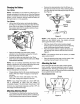
SECTION4: ASSEMBLING YOURGARDEN TRACTOR Antidote: EXTERNAL--Flush Unpacking • • • • • • • Remove all screws and staples from top of crate using a 1/4" hex head socket or a screw driver. To remove ends, grasp top board on the end, and pull towards you in a downward motion. (A hammer may be helpful). Set panel aside to avoid tire punctures. Repeat procedure for each side of the crate. Remove and discard plastic bag which covers unit.
Remove the steering bellow from the lift lever on the right hand side of tractor. Place steering bellow over the steering shaft extending through the dash. See Figure 3. ChargingtheBattery Type A Battery NOTE: If the battery on your tractor is of the A type, it is already activated and is ready to use. Skip the following section of assembly and proceed to Attaching Steering Wheel You will, however, need to install the battery on the tractor later on in the assembly. Hex Lock "_ Steering Wheel Cap .
• Remove the four screws which secure the seat to AttachingDeckLinks the seat pivot bracket. (Hardware A) NOTE: If the seat was shipped in a box, remove four screws from the bottom of the seat and place the seat in position against the seat pivot bracket. • The three adjustable deck links have been shipped unassembled. Attach as follows. • Turn the seat around and place in position against the seat pivot bracket, lining up the slotted holes in the pivot bracket with the holes in the seat.
• • • • Movethetractorlifthandleallthewaybacktothe fullraisedposition.Turnthetractorsteeringwheel allthewaytotheright. 50" Decks:Removetherollerassembly fromthe rearofthedeckandsetaside. Thetwodeckstabilizers andthediagonalbrace whichareattached tothefrontofthedeckare foldedbackoverthedeckforshippingpurposes. Unfoldthematthistime.SeeFigure9. Slidethedeckunderthetractorfromtheleftside. Youmayneedtoanglethedeckslightlytogetthe bracespastthefrontwheel.
hairpin clips just removed, using the lowest hole location on each side of the deck. See Figure 12. Move the lift lever forward to the lowest position. Attach the two rear lift links with flat washers and 50" Deck only: ,\ hairpin clips. Place deck belt around the engine pulley. Make certain the deck belt is seated in the deck pulley.
It may be necessary to pull up on the hold-down rods in order to start the wing nuts any circumstances is 30tirep.s.L Equalunder tire WARNING: Maximum pressure pressure should be maintained on all tires. _, Type B Battery Levelingthe Deck NOTE: The positive battery terminal is marked Pos. (+). The negative battery terminal is marked Neg. (-). After attaching the deck to the tractor, make sure it is adjusted properly.
SECTION5: KNOWYOURGARDEN TRACTOR This section is meant to acquaint you with the various types of controls and switches available on these tractors. Please read this section carefully and know your tractor better before starting to operate it. As with any power equipment, it is extremely important to ensure proper and safe operation of the tractor by following the instructions closely. Note that this manual covers various models and many controls, listed here, may be optional items.
Power Take-Oft (PTO) Lever Parking Brake The PTO lever is located on the right side of the dashboard. The PTO lever is used to engage and disengage the power to the attachments. To engage the PTO, lift the lever slowly and lock it into the notch. See Figure 20. The parking brake is located in front of the shift lever as shown in Figure 21. To set the parking brake, depress the clutch-brake pedal and pull up the parking brake knob. It will stay in the raised position.
SECTION6: OPERATING YOURGARDEN TRACTOR or starting unless the clutch-brake pedal is depressed and the PTO lever is in the disengaged position. In addition, the PTO lever must be in the disengaged position when the unit is put into reverse or the engine will shut off. If the operator leaves the seat with the PTO lever engaged and/or without setting the parking brake, the engine will automatically shut off.
Placetheshiftleverinoneofthetwoforward positions(LOWor HIGH),orin REVERSE. Place thespeedcontrolleverindesiredposition.Usefirst speedpositionwhenoperating thetractorforthe firsttime. ,_ • • • • When stopping the unit to empty a grass bag, etc., follow the instructions above. This procedure will also eliminate "browning" the grass, which is caused by hot exhaust gases from a running engine.
SECTION7: MAKINGADJUSTMENTS • ,_ wire(s) and ground against the WARNING: Disconnect theengine spark before plug performing any adjustments, repairs or maintenance. • Levelingthe Deck • • The sides of the deck should be the same distance from the ground. The front of the deck should be 1/4" to 3/8" lower than the rear of the deck. If adjustment is required, refer to "Leveling the Deck" in Assembly instructions.
• • • • • Threadthefrontspeedcontrollinkinor outofthe ferruleuntiltheholeinthelinklinesupwiththepin onthevariablespeedtorquebracket.Securewith theflatwasherandcotterpinremovedearlier. Pushtherearspeedcontrollinkbackward using lightpressure, andholditinthispositionasyou threaditintooroutoftheferruleuntiltheholeinthe linklinesupwiththepinonthevariablespeed torquebracket. • Models 820 thru 829 Only: Turn the link three more times (making it longer).
• • Ifthepapercannot be inserted, tighten the hex lock nut until the paper can be inserted through the coils. Release the parking brake and place the tractor in neutral. Depress the clutch-brake pedal and try rolling the tractor. The tractor should not move. If the tractor moves, repeat the above steps until proper brake adjustment is achieved. Hex Lock Nut Dimension "B" should be approximately 1/16-5/16" less than Dimension "A." See Figure 28. To increase Dimension "B," screw tie rod into tie rod end.
SECTION8: MAINTAININGYOURGARDEN TRACTOR CuttingBlades wire(s) and ground against the WARNING: Disconnect theengine spark before plug performing any adjustments, repairs or maintenance. ,_ gloves or a rag to grasp hands the cutting blades. WARNING: Protect by using heavy Lubrication The blades may be removed for sharpening or replacement as follows: Steering Gears Lubricate teeth of steering gears with automotive multipurpose grease after every 25 hours of operation or once a season. Refer to Figure 25.
NOTE: If you have operated the tractor for a long period, check the fluid level of the battery as it can overheat and lose fluid. rim generously. Never inflate to over 30 p.s.i, to seat beads. WARNING: Excessive pressure (over 30 p.s.i.) when seating beads may cause tire/rim assembly to burst with force sufficient to cause serious injury. Chargingthe Battery The engine is equipped with an alternator which charges battery when tractor is operated.
Rear Drive Belt • First remove the front drive belt as instructed in the Self-Tapping Self-Tapping Screws _ • Belt Keeper Assembly Engine • • • previous section. Disconnect the spring which secures the idler pulley to the frame. See Figure 32. Remove the transmission cover by unscrewing the two knobs and removing two machine screws. Roll the belt over the top of the transmission pulley. Remove belt from the variable speed pulley. Reassemble the new belt.
SECTION10: OPTIONALEQUIPMENT At the time of manufacture of tractor, the following optional equipment is available. Description Model No. Grass Collector For 46" Deck OEM-190-083 Mulching Kit For 46" Deck OEM-190-118 45" Two Stage Snow Thrower OEM-190-624 48" Dozer Blade OEM-190-840 42" Rear Dozer Blade** OEM-190-804 Agriculutral Traction Tires OEM-190-865 Tire Chains--23 x 9.5 OEM-190-964 100 lb.
SECTION11: TROUBLESHOOTING Trouble Engine will not crank Engine cranks but will not start Engine smokes Possible 1. Safety switch button not depressed. 2. Battery installed incorrectly. 3. Battery is dead or weak. 4. Blown fuse or circuit breaker. 5. Engine ground wi_loose. 1. Throttle or choke not in 1. 2. 3. starting position No fuel to the carburetor Fuel line or in-line fuel filter plugged 2. 3.
YOURNOTES Date Comments 26
YOURNOTES Date Comments 27
MANUFACTURER'S LIMITED WARRANTY The limited warranty set forth below is given by MTD PRODUCTS INC ("MTD") with respect to new merchandise purchased and used in the United States, its possessions and territories. MTD warrants this product against defects in material and workmanship for a period of two (2) years commencing on the date of original purchase and will, at its option, repair or replace, free of charge, any part found to be defective in material or workmanship.