INSTALLATION - USER - MAINTENANCE MANUAL EN i-KI MTD air/water heat pump, heating only, with DC inverter-driven compressors, domestic hot water production, axial-flow fans and hydronic unit for outdoor installation i-KIR MTD reverse-cycle air/water heat pump with DC inverter-driven compressors, domestic hot water production, axial-flow fans and hydronic unit for outdoor installation i-KI MTD / i-EM2 i-KIR MTD / i-EMR2 0011m ÷ 0061m
U I A INDEX U I A General warnings 3 I A General technical data 31 U I A Waiver of liability 3 I A Operating limits 32 U I A Fundamental safety rules 3 A Checking and starting up the unit 34 Receiving and handling the product 4 A Description of room controller buttons and display 36 Unit identification 6 A I A Operation and functions of the room controller 37 Description of standard unit 7 A I Control and operating characteristics 46 Dimensioned drawings 8 I System conf
GENERAL WARNINGS These appliances have been designed to chill and/or heat water and must be used in applications compatible with their performance characteristics; these appliances are designed for residential or similar applications. Incorrect installation, regulation and maintenance or improper use absolve the manufacturer from all liability, whether contractual or otherwise, for damage to people, animals or things.
I A RECEIVING AND HANDLING THE PRODUCT VISUAL INSPECTION STORING THE UNITS When the items are consigned by the carrier: - make sure that the goods delivered correspond to the description on the delivery note, comparing this against the data on the packaging label. - make sure the packaging and the unit are intact. The units must be stored sheltered from direct sunlight, rain, wind or sand.
I A RECEIVING AND HANDLING THE PRODUCT REMOVING THE PACKAGING The packaging must be removed by the operator using suitable protective equipment (gloves, glasses, etc.). Take special care not to damage the unit. Observe the local standards in force as regards disposal of the packaging, using specialist collection or recycling centres. The installation - user - maintenance manual is an integral part of the unit and should therefore be read and kept carefully.
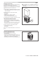
U I A UNIT IDENTIFICATION The heat pump can be identified from: Packaging label PACKAGING LABEL Describes the product identification data Packaging label RATING PLATE Describes the unit technical and performance specifications. Shows the serial number used to uniquely identify the unit. The serial number is also used to identify the unit’s spare parts.
I A DESCRIPTION OF STANDARD UNIT These air cooled reverse-cycle chillers with axial-flow fans operate with R410A refrigerant fluid and are suitable for outdoor installation. The units are CE marked, as established by the EU direcHEAT PUMP i-KI / i-KIR 0011m tives, including the latest amendments, and the corresponding approximated national legislation. They are factory tested and on site installation is limited to water and electrical connections.
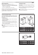
U I A DIMENSIONAL DRAWINGS INSIDE MODULE i-EM2 / i-EMR2 Anchoring foot 75 HEAT PUMP i-KI / i-KIR 0011m 43 327 57 73 15,3 300 42 R3/4(20A) 6 771 54 Water inlet 411 825 580 122,5 HEAT PUMP i-KI / i-KIR 0031m 275 90 60 357 330 Anchoring foot 333 116 122,5 16 388 Water outlet 155 540 155 180 110 335 881.5 Water outlet 522.
U I A MINIMUM CLEARANCES Mor e th an 1 e Mor than 100 More than 300 mm HEAT PUMP 0031m More than 300 mm HEAT PUMP 0011m mm Mor 00 m m e th an 1 00 m e Mor than 120 mm m Wiring cover Wiring cover Mor e Mor tha 0 n 60 e th an 6 mm Mor 00 m m Mor HEAT PUMP 0061m e than m 600 00 m 00 m m e Mor than 100 100 mm m 400 an 1 More than 300 mm e th an 6 INSIDE MODULE i-EM2 / i-EMR2 100 Mor e th m e th Mor an 6 00 m m Mor e th an 6 00 m m EN 10/2010 i-KI
HEAT PUMP INSTALLATION I A CHOICE OF INSTALLATION SITE Before installing the unit, agree with the customer the site where it will be installed, taking the following points into consideration: • Check that the fixing points are adequate to support the weight of the unit; • Pay scrupulous respect to safety distances between the unit and other equipment or structures to ensure that air entering the unit and discharged by the fans is free to circulate.
I A HEAT PUMP INSTALLATION CHOICE OF INSTALLATION SITE Before installing the unit, agree with the customer the site where it will be installed, taking the following points into consideration: • the unit must be installed indoors; • the unit must be installed by fastening to a vertical wall • safety distances between the unit and other equipment • careful attention must be paid to structures so as to ensure sufficient ventilation.
I A WATER CONNECTIONS The choice and installation of components is the responsibility of the installer who should follow good working practice and current legislation. Before connecting the pipes, make sure they do not contain stones, sand, rust, dross or other foreign bodies which might damage the unit. Construction of a bypass is recommended to enable the pipes to be washed through without having to disconnect the unit (see drain valves).
I A WATER CONNECTIONS Probe socket fittings - Remove the protective caps from the water connections - Install the probe socket fittings supplied on the system circuit inlet and return. For i-KI/i-KIR 0011m units, install the 1"-3/4" reducers as standard between the probe socket fittings and water connections. To fasten the probe socket fittings use two spanners. Place probe BT1 on the inlet connection and BT2 on the outlet connection.
I A WATER CONNECTIONS System circuit connection • Use a flat gasket to ensure tightness • Connect the flexible joints to the probe socket fittings installed on the heat pump • Connect the system pipes to the flexible joints • Use two spanners to tighten the water connections • Install the filter on the system return pipe The expansion vessel pre-charge pressure depends on the height the heat pump is installed at. To determine the pre-charge value, proceed as follows: Vessel pre-charge = H + 0.
I A WATER CONNECTIONS Condensate drain The unit is fitted with condensate pan; this must be connected to a drain system to take away the water that forms, see the drawing. In heating mode the unit produces a significant quantity of condensate, which must be suitably drained. Proceed as follows: • Connect the unit condensate drain • Make sure the drain hose has a incline of at least 2 cm/m, without obstructions or choking. • Connect the condensate drain hose to a rainwater drain.
I A ELECTRICAL CONNECTIONS The heat pumps must be installed downstream of a main switch (QF1, see wiring diagram), as required by the standards in force in the country where the unit is installed. Connection to the mains power supply and the connection of the flow switch to the corresponding terminals must be performed by authorised personnel in compliance with the standards in force. For all electrical work, refer to the electrical wiring diagrams in this manual.
I A ELECTRICAL CONNECTIONS Strip the end of the connection cables according to the measurements shown in the following drawing. WARNING The connection cable must be stripped along a 10 mm section. If this section is shorter, contact may be defective. Longer sections may cause short-circuits. • Use a residual current circuit breaker with a gap of around 3 mm between contacts. • Poor wiring may not only cause malfunctions but also damage to the PC board. • Suitably tighten all the screws.
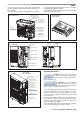
I A MAINS POWER SUPPLY CONNECTIONS - Before connecting the unit to the mains power supply, make sure that for each connection to the mains power supply switch QF1 is open (“OFF”). 1 ON OFF - Remove the protective cover from the heat pump terminal block by unscrewing the fastening screw. 2 Wiring cover Screw - Remove the protective cover from the electrical panel on the inside module by unscrewing the fastening screws and removing the cover.
I A MAINS POWER SUPPLY CONNECTIONS - Make sure that all the protective devices removed to make the electrical connections have been repositioned before powering up the unit. - Reposition the wiring cover on the heat pump and the cover on the inside module and fasten them to the unit - For all mains power connections, move the main switch QF1 (outside the appliance) to “ON”.
I A INSTALLER CONNECTIONS TO BE PERFORMED ON THE INSIDE MODULE Below is a list of the electrical connections that the installer needs to complete for the INSIDE MODULE only. The maximum length of probe cables is 100 m for 1 mm2 cables, and 50 m for 0.5 mm2 cables. Outside air probe (BT11) connection / 1 2H Installation instructions The outside air probe must be installed: • outside of the home • not in direct sunlight, away from flue gas discharges, air outlets, or doors and windows.
I A INSTALLER CONNECTIONS TO BE PERFORMED ON THE INSIDE MODULE A5 room controller connection Installation instructions The room controller must be installed in the best reference position for temperature control. Position the room controller as follows: • around 1.5 metres from the floor, in a part of the room that allows the sensor to accurately measure the room temperature; • away from cold air flows, sunlight or other sources of heat.
I A INSTALLER CONNECTIONS TO BE PERFORMED ON THE INSIDE MODULE • Close the cover A1 and secure it with the screw A2 • Plug in the 4-pin connector, figure (7) • Replace the terminal, starting with the lower tabs, applying a hinge movement. Make sure that the electrical wires are inside to ensure correct fastening (click on). • Dimensions of A5 room controller figure (8).
I A INSTALLER CONNECTIONS TO BE PERFORMED ON THE INSIDE MODULE Solution 2 System with heat pump and outlet electric heater WITHOUT storage tank. Position probe BT9 on the system outlet pipe. 2 6 7 43 44 BT9 230V / 400V N Outlet electric heater control A) REPLACEMENT: The electric heater is enabled when the outside temperature is less than the value of parameter 0304 and the compressor is off, figure 3. To enable heater activation in REPLACEMENT mode set parameter 0303 = 1 and 010G = 1.
I A INSTALLER CONNECTIONS TO BE PERFORMED ON THE INSIDE MODULE Supplementary heating always enabled Supplementary heating with the electric heater is enabled for all outside air temperatures. To enable heating at all times set parameter 0303 = 0 and 010G = 0 Electric heater operation reflects the trend in water outlet temperature, as shown on the graph in figure 4.
I A INSTALLER CONNECTIONS TO BE PERFORMED ON THE INSIDE MODULE KM2 Boiler 1 A boiler can be used as a supplementary or replacement heat source for the system. 6 7 43 44 Solution 1 System with heat pump and boiler with storage tank. BT9 Boiler Solution 2 System with heat pump and boiler without storage tank. 2 6 7 43 44 BT9 Boiler Boiler control A) REPLACEMENT: the boiler is only enabled if the outside air temperature is less than the value of parameter 0307 and the compressor is off, figure 3.
I A INSTALLER CONNECTIONS TO BE PERFORMED ON THE INSIDE MODULE Supplementary heating always enabled Supplementary heating by boiler is enabled for all outside air temperatures. To enable heating at all times set parameter 0306 = 0 and 010H = 0 Boiler operation reflects the trend in water temperature, as shown on the graph in figure 4.
I A INSTALLER CONNECTIONS TO BE PERFORMED ON THE INSIDE MODULE KM4 DHW storage electric heater An electric heater can be managed for heating the DHW storage. 10 11 DHW storage electric heater control The electric heater is activated to reach a temperature value that the heat pump on its own is not able to reach. N U Example: Domestic hot water temperature produced with heat pump 0023 = 55°C Domestic hot water temperature produced with electric heater 0209 = 65°C.
I A INSTALLER CONNECTIONS TO BE PERFORMED ON THE INSIDE MODULE HL1 Configurable contact This contact can be configured for the following functions: • Alarm signal • Secondary circuit pump • Dehumidifier Alarm signal A visual or audible signal device can be activated if the unit shuts down due to a malfunction.
I A INSTALLER CONNECTIONS TO BE PERFORMED ON THE INSIDE MODULE SA2 Remote cooling/heating Cooling/heating operating mode can be managed from a remote control unit. If remote cooling/heating changeover is enabled, the operating mode cannot be changed on the keypad. 27 28 Set the following parameters: Description Enable remote contact 0= remote contact enabled 1= remote contact disabled (only from keypad) Menu Parameter Value to be no.
I A INSTALLER CONNECTIONS TO BE PERFORMED ON THE INSIDE MODULE SA5 Reduced electricity rate contact Forced refilling of the reserve storage tanks can be activated based on different electricity rates during the day. During reduced rate periods, the heat pump can be forced on so as to heat the domestic hot water or system storage tank, where fitted.
I A GENERAL TECHNICAL DATA Rated heating capacity Total power consumption COP EN14511 Cooling capacity Total power consumption EER EN14511 Heating capacity Total power consumption COP EN14511 Cooling capacity Total power consumption EER EN14511 ESEER 1 1 1 2 2 2 3 3 3 4 4 4 4 0011m 6,00 1,46 4,11 i-KI 0031m 9,55 2,38 4,02 0061m 15,70 3,83 4,10 5,30 1,74 3,05 9,00 2,90 3,10 14,70 4,55 3,23 DC inverterdriven rotary Scroll DC Inverter V-ph-Hz dB(A) dB(A) 1 R410A 1,05 1 Ci 230-1-50 60 46 mm mm mm
I A OPERATING LIMITS COOLING Outside air temperature (°C) 45 40 35 30 25 20 15 0 5 10 15 20 25 Water outlet temperature (°C) Outside air temperature (°C) HEATING 50 45 40 35 30 25 20 15 10 5 0 -5 -10 -15 -20 -25 15 25 35 45 55 65 Water outlet temperature (°C) Min/max water temperature difference = 5/10 °C (in minimum flow conditions, 7 l/min) MAX return temperature to heat pump = 55°C MAX outlet temperature to heat pump for DHW production = 58°C Water circuit pressure min/max = 1/3 bar Maxim
I A OPERATING LIMITS PUMP CHARACTERISTICS 0011m [kPa] 120 110 100 90 80 70 60 50 40 30 20 10 0 0031m [kPa] 80 70 60 50 40 30 20 10 0 0061m 1 2 3 4 5 6 7 8 9 10 11 12 13 14 15 16 17 18 19 20 [L/min] 2 4 6 8 10 12 14 16 18 20 22 24 26 28 30 32 34 36 38 40 [L/min] [kPA] 130 120 110 100 90 80 70 60 50 40 30 20 10 0 0 5 10 15 20 25 30 35 40 45 50 [L/min] The pressure head values refer to the values available at the water connections.
A CHECKING AND STARTING UP THE UNIT CHECKS BEFORE STARTING THE UNIT • the vibration damping feet are fitted • inlet filters are fitted on the system • suitably-sized expansion vessel and safety valve installed on the DHW circuit • an expansion vessel is installed if the expansion vessel on the unit is undersized • make sure vibration damper joints are installed on water connections • a low-loss header is installed if the water content is insufficient • make sure the position of the outside air probe corre
A CHECKING AND STARTING UP THE UNIT • Once having powered up the heat pump, the display on the room control unit shows this message (1): 1 • Followed by (2): 2 • Wait a few minutes, the unit is ready to operate when the display shows (3): 3 Before starting up, power up the unit for at least two hours, with the compressor off, so as to allow the oil in the compressor sump to heat up. When commissioning the heat pump, the user must configure the type of system.
DESCRIPTION OR ROOM CONTROLLER BUTTONS AND DISPLAY BUTTONS 5 mode 1 NO.
A OPERATION AND FUNCTIONS OF THE ROOM CONTROLLER Meaning of the symbols Symbol Meaning Press and release x3 sec. Hold for 3 seconds Turn the knob Display During normal operation of the unit, the display shows the following information: 1 2 3 4 5 operating mode selected domestic hot water production enabled room temperature hour and minutes day 1 2 3 4 5 Additional information displayed During operation of the unit, pressing the knob displays the information described below.
A OPERATION AND FUNCTIONS OF THE ROOM CONTROLLER Setting the time and date 1 2 3 x3 sec. Press the button for 3 seconds 4 Press the knob 5 • Press the knob to confirm 7 • The minutes flash • Turn the knob to select the minutes value 8 • The day flashes • Turn the knob to select the day** • Press the knob to confirm • The hours flash • Turn the knob to select the hour value 6 • Press the knob to confirm 9 • Press the button to exit.
A OPERATION AND FUNCTIONS OF THE ROOM CONTROLLER Switching ON The button enables operation of the pump or the zone valve controlled by the room controller, the heat pump is activated by selecting the operating mode using the button, as shown below. 1 2 3 x3 sec. ZONE OFF Press the ZONE ON** button for 3 seconds ** The heat pump is not yet operating, the mode has to be selected: heating, cooling, auto or domestic hot water production. Selecting the operating mode None No operating mode selected.
A OPERATION AND FUNCTIONS OF THE ROOM CONTROLLER Domestic hot water production 1 2 Domestic hot water production not enabled Press the 3 • Domestic hot water production enabled • The symbol is displayed . Selecting the domestic hot water set point The domestic hot water temperature is measured by the probe installed inside the DHW storage tank. 1 2 • Press thei seconds 4 x3 sec.
A OPERATION AND FUNCTIONS OF THE ROOM CONTROLLER 10 11 • Press the button twice until reaching the main display.
A OPERATION AND FUNCTIONS OF THE ROOM CONTROLLER Programming the time bands The room controller can customise on/off times for each zone in the system, based on six time bands. The six time bands are identified by the following symbols, selected by turning the knob: Time band 1 Time band 2 Time band 3 Time band 4 Time band 5 Time band 6 The time bands on systems with multiple zones, each of which is managed by its own room controller (maximum 6), must be programmed on each room controller.
8 + 9 .... 10 .... 11 12 13 14 • Press the button twice until reaching the main display.
A OPERATION AND FUNCTIONS OF THE ROOM CONTROLLER Switching OFF The button disables operation of the pump or the zone valve controlled by the room controller, the heat pump is deactivated using the button, as shown in " Selecting the operating mode". 1 2 3 x3 sec.
A OPERATION AND FUNCTIONS OF THE ROOM CONTROLLER 4 5 6 A B • Press the knob to confirm 7 A Turn the knob to select the menu B Press the knob to confirm • Turn the knob and select the parameter to be set 8 9 • Press the knob • The parameter value flashes • Turn the knob to change the parameter value 10 11 • Press the button twice until reaching the main display • Main display Press the • Press the knob to confirm button to exit programming mode EN 10/2010 i-KI MTD / i-KIR MTD 45
A CONTROL AND OPERATING CHARACTERISTICS Temperature control The heating or cooling circuit water outlet temperature is calculated by the controller and depends on the following factors: A) system outlet set point compensation in heating or cooling (see paragraph) B) room temperature influence (see paragraph) C) minimum and maximum outlet temperature limit (see paragraph) D) room temperature set point A) System water outlet temperature set point compensation The water outlet temperature set point in heatin
A CONTROL AND OPERATING CHARACTERISTICS Example referred to compensation curve 1.0 The compensation curve determines the water outlet temperature in heating; this may then be corrected based on the difference between the desired room set point and the actual room temperature. The correction made to the outlet temperature depends on the “Room Authority” coefficient. The higher the value of the Room Authority the higher the correction to the system outlet temperature, and vice-versa.
A CONTROL AND OPERATING CHARACTERISTIC Water outlet set point compensation diagram in COOLING The compensation curve in cooling mode can be modified to allow correct heat pump operation depending on the cooling system used (radiant panels, fan coils). Points T1 and T2 correspond to two outside temperature values that respectively identify the maximum and minimum system outlet temperature. Outlet set point Tm1 Tm2 Te1 Te2 Outside temp.
A CONTROL AND OPERATING CHARACTERISTICS Automatic mode changeover based on outside temperature In mode, the operating mode (heating / cooling) changes automatically, avoiding the need for the user to change the mode manually. Mode changeover is based on the diagram shown in the figure. The centre zone A corresponds to an area of inactivity, as the outside climate conditions mean neither heating nor cooling is required.
U I A CONTROL AND OPERATING CHARACTERISTICS Heat pump operation with fixed set point Description Outlet water set point compensation using the compensation curves can be disabled. To enable fixed set point operation, set parameter 0152=0 and 0154=0 The heat pump will operate based on the fixed outlet set point defined by parameters 0153 (Heating) and 0155 (cooling).
U I A SYSTEM CONFIGURATION The heat pump controller can select configurations for 15 different types of system by setting parameter 0101. The following table describes the system configurations available.
Water circuit diagram (not a working drawing) i-KI MTD / i-KIR MTD EN 10/2010 2 OUTSIDE 3 T INDICATES ACCESSORIES ELECTRICAL CONNECTIONS DOMESTIC COLD WATER DOMESTIC HOT WATER HEAT PUMP RETURN HEAT PUMP OUTLET SAFETY VALVE WITH PIPED DISCHARGE 10 T T F INSIDE 4 N.C. MEMBRANE EXPANSION VESSEL DRAIN VALVE “Y” FILTER SHUT-OFF VALVE THERMOSTATIC MIXER VENT VALVE MT CALIBRATING VALVE VIBRATION DAMPER JOINT FLOW SWITCH THERMOMETER N.B.: Typical water circuit diagram.
U I A SYSTEM CONFIGURATION Parameter configuration Menu Parameter no.
Water circuit diagram (not a working drawing) i-KI MTD / i-KIR MTD EN 10/2010 2 OUTSIDE 3 T INDICATES ACCESSORIES ELECTRICAL CONNECTIONS 10 T T F INSIDE 4 N.C. MEMBRANE EXPANSION VESSEL HOT WATER RECIRCULATION DOMESTIC COLD WATER DOMESTIC HOT WATER HEAT PUMP RETURN HEAT PUMP OUTLET SAFETY VALVE WITH PIPED DISCHARGE “Y” FILTER DRAIN VALVE SHUT-OFF VALVE THERMOSTATIC MIXER CALIBRATING VALVE VENT VALVE MT VIBRATION DAMPER JOINT FLOW SWITCH THERMOMETER N.B.
1 3 T OUTSIDE Black Blue OUTSIDE AIR PROBE TERMINAL BLOCK 10 INSIDE Brown 5 10 11 1 41 42 D A5 51 52 53 54 55 Ausiliary contact 230V 50 Hz 21 22 L 9 12 13 2 45 46 TxRx+ HL1 Yellow/Green KM4 SELECTOR VALVE TERMINAL BLOCK TxRx- BT8 Red YV5 Blue BT11 INSIDE MODULE INSTALLER TERMINAL BLOCK (CONTACTS USED) Brown GND Green GND 24 VAC Black 6 7 230V 50 Hz N 1 2 T1 T2 N 11 21 31 ELECTRIC HEATER TERMINAL BLOCK U ELECTRIC HEATER PANEL TERMINAL BLOCK 8 24V AC L N A
U I A SYSTEM CONFIGURATION System number 0 Parameter configuration Description Menu Parameter no.
U I A REGOLAZIONE IMPIANTO MAINTENANCE AND SERVICE E CARATTERISTICHE DI FUNZIONAMENTO Alarm signals When an alarm is activated, the symbol comes one. Displaying alarms 1 2 3 x3 sec. • Press the onds and buttons for 3 sec- • Turn the knob • Display the alarm codes • Press the knob to confirm • Resolve the problem and then reset the alarms using the procedure described in “Resetting alarms” Resetting alarms 1 2 3 x3 sec.
A MAINTENANCE AND SERVICE TABLE OF REMOTE KEYPAD ALARMS Alarms displayed on the remote keypad.
I A MAINTENANCE AND SERVICE TABLE OF ALARMS ON HEAT PUMP DISPLAY Alarms shown on the board display (PCB Display) located in the compressor compartment. ERROR CODE - FEATURES, PARTS, COMPONENTS MALFUNCTIONING POWER SUPPLY CHECKS Check the power supply SOLUTION Verify the power supply If CF3 is blown, replace it and check if there is a short-circuit on a connector on the 4-way valve, frost protection heater, expansion vessel or circulating pump. If a short-circuit is found, replace the components.
I A MAINTENANCE AND SERVICE ERROR CODE A6 A7 A8 C0 C2 C1 FEATURES, PARTS, COMPONENTS MALFUNCTIONING Return temperature probe error COMPRESSOR SUCTION TEMPERATURE PROBE Defrost temperature probe error DEFROST PROBE Outlet temperature probe error COMPRESSOR DISCHARGE TEMPERATURE PROBE Power supply module error Outside temperature probe error Upper fan motor error (*1) POWER SUPPLY MODULE Lower fan motor error (*1) 0031 0011 0031 Replace the probe if faulty 0011 0031 Replace the probe if faulty
I A MAINTENANCE AND SERVICE FEATURES, PARTS, COMPONENTS MALFUNCTIONING P3 High pressure switch error U5 Below-normal temperature measured CIRCULATING PUMP PRINTED CIRCUIT BOARD (PCB) (*1) WATER PUMP BLOCKED WATER CIRCUIT BLOCKED High pressure switch The unit should not be operated below -20°C to protect the various components Check resistance using a tester OUTSIDE TEMPERATURE PROBE [see table 1] THE OUTSIDE TEMPERATURE FALLS BELOW -20°C 4-WAY VALVE OUTSIDE AIR RECIRCULATION No cooling No heating
A MAINTENANCE AND SERVICE Resetting alarms displayed by the board on the unit Press the PUMP SW and RESET SW buttons at the same time for 5 seconds to reset the alarm. The alarms are reset automatically no operations are carried out for 5 minutes. While an error code is being displayed, holding the reset button for 10 seconds or more resets the alarm log.
A SCHEDULED MAINTENANCE Never perform any cleaning operations before having disconnected the unit from the mains power supply. Make sure power is not connected before proceeding. Control maintenance is fundamental to maintain the efficiency of the unit both in terms of operation and energy consumption.
U I A LIST OF PARAMETERS Description Menu Parameter no.
U I A LIST OF PARAMETERS Description Menu Parameter no.
U I A INSTALLER OPERATIONS CHECKLIST Installer: __________________________________________ Designer: _______________________________________ Type of application:___________________________________________________________________________________ Street ___________________________________________________________________________ number _____________ City/town __________________________ Postcode/ZIP code _____________ Province/State _________________________ Unit model installed ______________________________
U I A INSTALLER OPERATIONS CHECKLIST CONCERNING UNIT INSTALLATION OPERATIONS AND SETUP FOR COMMISSIONING HAVE THE FOLLOWING CHECKS BEEN COMPLETED? Components installed (as described in the paragraph on "Water circuit connections") YES NO • Two pressure gauges with a suitable scale are installed on the inlet and outlet ❑ ❑ • Shut-off valves are installed on the heating system circuit and domestic hot water circuit inlet and outlet ❑ ❑ • Two thermometers are installed, on the inlet and outlet ❑ ❑
U I A INSTALLER OPERATIONS CHECKLIST Checks (as described in the paragraph on "Checking and starting up the unit") CHECKED • The connection pipes are suitably supported so that these do not weigh on the appliance ❑ • Correct sizing of the expansion vessel has been verified according to the system water content and the expected operating temperature ❑ • The position of the outside air temperature probe complies with the information provided in the installation manual ❑ • The position of the room con
COD. C01002064C_01 Climaveneta S.p.A. Via Sarson 57/c 36061 Bassano del Grappa (VI) Italy Tel +39 0424 509500 Fax +39 0424 509509 info@climaveneta.com www.climaveneta.com Climaveneta France 3, Village d’Entreprises ZA de la Couronne des Prés Avenue de la Mauldre 78680 Epone France Tel +33 (0)1 30 95 19 19 Fax +33 (0)1 30 95 18 18 info@climaveneta.fr www.climaveneta.fr Climaveneta Deutschland Rhenus Platz, 2 59439 Holzwickede Germany Tel +49 2301 91222-0 Fax +49 2301 91222-99 info@climaveneta.de www.