Operator’s Manual Electric Lawn Mower 13” Rear Bagger Model C06 IMPORTANT: READ SAFETY RULES AND INSTRUCTIONS CAREFULLY UL ® This symbol on the product’s nameplate means it is listed by UNDERWRITERS LABORATORIES INC. MTD LLC P.O. BOX 361131 CLEVELAND, OHIO 44136-0019 FORM NO. 770-10502C.
TABLE OF CONTENTS Content Important Safe Operation Practices Slope Gauge Contents of Hardware Pack Assembling Your Lawn Mower Know Your Lawn Mower Operating Your Lawn Mower Page 3 6 7 7 11 12 Content Making Adjustments Maintaining Your Lawn Mower Off Season Storage Trouble Shooting Illustrated Parts List Warranty Page 13 14 15 16 18 20 FINDING MODEL NUMBER This Operator’s Manual is an important part of your new lawn mower. It will help you assemble, prepare and maintain the unit for best performance.
SECTION 1: IMPORTANT SAFE OPERATION PRACTICES READ ALL INSTRUCTIONS! WARNING: This symbol points out important safety instructions, which if not followed, could endanger the personal safety and/or property of yourself and others. Read and follow all instructions in this manual before attempting to operate this machine. Failure to comply with these instructions may result in personal injury. When you see this symbol—HEED ITS WARNING.
16. Home circuit – This mower should be operated on a 15 AMP circuit. If you experience difficulty in starting with a standard 15 AMP fuse or circuit breaker, contact your nearest authorized service facility. Do not use a higher rated fuse or breaker without consulting your power company. 17. Do not abuse the cord by pulling the mower by the cord or yanking it to disconnect it from the receptacle. Keep cord from heat, oil, and sharp edges. 18.
Service 1. 2. 3. 4. 5. 6. 7. 8. 9. 10. Never tamper with safety devices. Check their proper operation regularly. 11. After striking a foreign object, stop the motor and disconnect the power cord. Thoroughly inspect the mower for any damage. Repair the damage before operating the mower. 12. Grass catcher components, discharge cover, and trail shield are subject to wear and damage which could expose moving parts or allow objects to be thrown.
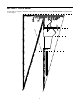
SECTION 2: SLOPE GAUGE Use this page as a guide to determine slopes where you may not operate safely. Do not operate your lawn mower on such slopes.
SECTION 3: CONTENTS OF HARDWARE PACK Hardware pack may contain extra items which are not used on your unit. Part numbers are shown in parentheses.
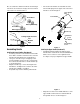
• Also, be certain the smaller front wheels and the larger rear wheels are mounted correctly to the front and rear of the mower as shown in Figure 1. Once both lower handles are installed, insert the lower handle plugs into the upper ends of the lower handles as shown in Figure 2.
• • • • • • On the left side, install the lock washer and hex nut and tighten finger tight. On the right side, insert the hex bolt into the hex hole in the cord insulator. Install the lock washer and thread the hex nut onto the hex bolt. Make certain that the curved portion of the cord insulator is resting flush against the upper handle. Tighten the hardware firmly using an adjustable wrench or suitable tightening tool. Refer to Figure 3 for proper alignment of hardware and handles.
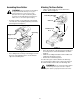
Assembling Grass Catcher Attaching The Grass Catcher • WARNING: Never operate the mower without the proper trail shield, discharge cover, grass catcher, blade/motor control or other safety protective devices in place and working. Never operate the mower with damaged safety devices. Failure to do so can result in personal injury. • Lift the rear discharge door on the back of the mower. Refer to Figure 8.
SECTION 5: KNOW YOUR LAWN MOWER Figure 9 Circuit Breaker Read this operator’s manual and safety rules before operating your lawn mower. Compare the illustration in Figure 9 with your lawn mower to familiarize yourself with the location of various parts and controls. Save this manual for future reference. The mower is equipped with a circuit breaker, located on the motor/blade control. Refer to Figure 9. This circuit breaker may trip when too much strain is placed on the mower.
SECTION 6: OPERATING YOUR LAWN MOWER Cord Connection Connecting to the Electric Power Source Extension Cord Selection WARNING: This mower should be operated Listed below are the lengths of extension cord and corresponding acceptable cord ratings. • 50’ Cord — use 16 AWG • 100’ Cord — use 14 AWG • 150’ Cord — use 12 AWG In all cases, the extension cord should be a UL listed cord set suitable for outdoor use. on a 15 AMP circuit.
Stopping the Motor and Blade T = Obstacles WARNING: The blade continues to rotate for a few seconds after the motor is shut off. If the motor does not come to a stop when the motor/blade control handle is released, contact an authorized service dealer. To stop the motor and blade from spinning: • Release the motor/blade control lever from its position against the upper handle and the blade and motor will quickly come to a stop.
• • Repeat this procedure for all wheels, being certain to mount them all in the same position at each corner. Failing to do this will produce an uneven cut. • Resetting the Circuit Breaker The mower is equipped with a circuit breaker, located on the motor/blade control assembly as shown in Figure 11. This circuit breaker may trip when too much strain is placed on the mower. The circuit breaker may have been tripped if the mower will not run.
Sharpening the Blade • To sharpen the blade, first remove the blade as outlined in the previous section. DO NOT attempt to sharpen the blade while it is attached to the mower. The blade can be sharpened with a file or on a grinding wheel. Mower Deck • • When sharpening the blade, follow the original angle of grind as a guide. It is extremely important that each cutting edge receives an equal amount of grinding to prevent an unbalanced blade.
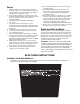
SECTION 10: TROUBLE SHOOTING GUIDE Trouble Possible Cause(s) Corrective Action Mower not starting. Cord disconnected from the motor/ blade control. Reconnect the cord keeping the cord restraint close to the motor/blade control. Motor/blade control switch defective. Replace motor/blade control switch. Extension cord not connected to a source of power. Connect the extension cord to a 110-120 volt 60 cycle A.C. receptacle. Circuit breaker on the mower or in the house receptacle tripped.
NOTES 17
SECTION 11: PARTS LIST FOR MODEL C06 18
Model C06 REF. NO. PART NO. DESCRIPTION 1 749-1042A Upper Handle 2 749-1312 Lower Handle 3 720-0369 Handle Plug 4 710-1718 Handle Bolt LH 5 736-0649 Lock Washer 6 712-0690 Hex Nut 7 710-1757 Screw 8 725-04075 Motor / Blade Control Switch 9 731-2427 Cord Insulator 10 731-2421-0638 Mower Housing (Incl.
MANUFACTURER’S LIMITED WARRANTY FOR: The limited warranty set forth below is given by MTD LLC with respect to new merchandise purchased and used in the United States, its possessions and territories. “MTD”warrants this product against defects in material and workmanship for a period of two (2) years commencing on the date of original purchase and will, at its option, repair or replace, free of charge, any part found to be defective in materials or workmanship.