Operator’s Manual Edger Models 520 550 551 554 Model 550 and 551 Shown IMPORTANT: READ SAFETY RULES AND INSTRUCTIONS CAREFULLY Warning: This unit is equipped with an internal combustion engine and should not be used on or near any unimproved forestcovered, brush-covered or grass-covered land unless the engine’s exhaust system is equipped with a spark arrester meeting applicable local or state laws (if any). If a spark arrester is used, it should be maintained in effective working order by the operator.
TABLE OF CONTENTS Content Important Safe Operation Practices Assembling Your Edger Know Your Edger Operating Your Edger Making Adjustments Page 3 5 6 7 7 Content Maintaining And Servicing Your Edger Off Season Storage Trouble Shooting Illustrated Parts List Warranty Page 10 12 12 13 20 FINDING MODEL NUMBER This Operator’s Manual is an important part of your new edger. It will help you assemble, prepare and maintain the unit for best performance. Please read and understand what it says.
SECTION 1: IMPORTANT SAFE OPERATION PRACTICES WARNING: THIS SYMBOL POINTS OUT IMPORTANT SAFETY INSTRUCTIONS WHICH, IF NOT FOLLOWED, COULD ENDANGER THE PERSONAL SAFETY AND/OR PROPERTY OF YOURSELF AND OTHERS. READ AND FOLLOW ALL INSTRUCTIONS IN THIS MANUAL BEFORE ATTEMPTING TO OPERATE THIS MACHINE. FAILURE TO COMPLY WITH THESE INSTRUCTIONS MAY RESULT IN PERSONAL INJURY. WHEN YOU SEE THIS SYMBOL — HEED ITS WARNING.
18. Only use parts and accessories made for this machine by the manufacturer. Failure to do so, can result in personal injury. 19. If situations occur which are not covered in this manual, use care and good judgment. Contact an authorized MTD service dealer or telephone 1-800800-7310. 4. Never operate with damaged safety devices. Failure to do so, can result in personal injury. 5. Never run an engine indoors or in a poorly ventilated area.
SECTION 2: ASSEMBLING YOUR EDGER IMPORTANT: This unit is shipped WITHOUT Upper Handle GASOLINE or OIL. After setting up the unit, service engine with gasoline and oil as instructed in the separate engine manual packed with your unit. NOTE: Reference to right or left hand side of the edger is observed from the operating position. Positioning the Edger Handles • • • Blade Control Bail Remove and discard any packaging cardboard that may be present between the upper handle and the lower handle.
SECTION 3: KNOW YOUR EDGER Blade Control Bail Blade Depth Control Lever (Transport Position Shown) Pull Rope / Recoil Starter Curb Height Adjustment Lever (If Equipped) Bevel Adjustment Lever (If Equipped) Primer Spindle Sheaves Belt Guard NOTE: Wheel and blade styles vary by model. Yours may differ slightly. Model 550 and 551 Shown. Figure 4 Blade Depth Control Lever WARNING: Be familiar with all controls and their proper operation. Know how to stop the machine and disengage them quickly.
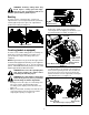
SECTION 4: OPERATING YOUR EDGER WEAR YOUR SAFETY GLASSES FORESIGHT IS BETTER THAN NO SIGHT • The operation of any edger can result in foreign objects being thrown into the eyes, which can result in severe eye damage. Always wear safety glasses or eye shields. We recommend wide vision safety mask for over spectacles or standard safety glasses WARNING: Do not lower blade if over concrete, asphalt, rocks or the blade can strike the supporting resulting in personal injury or damage.
Edging Along A Curb (models so equipped) • • NOTE: Edger features vary by model. All edger models do NOT come equipped to edge along a curb nor is there a curb wheel kit available to modify your edger if it was not purchased equipped to do so. Pivot the right, rear wheel into an applicable position in relation to the height of the curb to be edged along. Release the curb height adjustment lever to lock the wheel in position. See Figure 7.
WARNING: Rotating cutting blade may throw objects causing personal injury. Keep area clear of bystanders and do not operate without guards in place. Flange Lock Nut Beveling In order to achieve a bevelled edge, set the bevel adjustment lever (refer to Figure 8) in the first (left hand) or third (right hand) notch to place the edger blade in position for beveling. See Figure 9.
• • Install the flat washer (part no. 736-04088) and the triplex edger blade (part no. 781-0748) that are packed separately in the box. Secure with the bell washer and the hex lock nut removed earlier. See Figure 13. IMPORTANT: Make certain that the drive belt is seated correctly on the blade spindle and that it is riding smoothly on the spindle sheaves and is not pinched between them. Repeat the first three steps if the belt is pinched.
Replacing the Edger Blade Flange Lock Nut WARNING: The edger blade is sharp. Wear leather work gloves to protect your hands when working around the edger blade. Engine Flywheel Pulley WARNING: Disconnect the spark plug wire and ground against engine before performing the following steps. • • • • • • Working in front of the edger, loosen the flange lock nut on top of frame, allowing the idler pulley assembly to pivot slightly out from the frame. See Figure 16.
SECTION 7: OFF-SEASON STORAGE • Observe the following when preparing the edger for long-term storage: • • • Clean and lubricate unit thoroughly as instructed on page 10 of this manual. Refer to the Engine Manual packed separately with the edger for engine manufacturers’s storage instructions. Coat the edger blade with chassis grease to prevent rusting and corrosion. • Store the edger in a dry, clean area. Do not store next to any corrosive materials, such as lawn fertilizer.
SECTION 9: PARTS LIST FOR MODEL 520/550/551/554 HANDLE 19† 15 8 20 14 11 18 6 5 1 17 7 13 10 3 16 12 2 9 11 6 4 REF. NO. 1 2 3 4 5 6 7 8 9 10 11 PART NO. 710-3103 710-0449 710-1205 710-3008 710-0606 712-3004A 720-0279 720-0142 720-0241 732-0369 736-0451 REF. PART NO. NO.
Model 520/550/551/554 Frame 2 10 5 6 9 3 15 11 13 14 12 7 8 4 1 REF. NO. 1 2 3 4 5 6 7 8 9 10 11 12 13 14 15 PART NO. 710-0191 710-0599 710-0654A 710-0944 712-0431 731-04168 736-0320 736-0452 736-3052 736-3090 750-04142 756-0313 756-1035A 756-1150A 787-01072 DESCRIPTION Screw, 3/8-24 Screw, 1/4-20 Screw, 3/8-16 Screw, 3/8-16 Flange Lock Nut, 3/8-16 Debris Guard Flat Washer, 3/8 ID x 1.37 OD Bell Washer,.396 x 1.140 Flat Washer,.406 x 1.00 Flat Washer,.260 x.
Model 520 Spindle Assembly 28† 11 7 17 8 29† 18 16 10 19 25 21 17 20 9 1 3 27 15 7 17 22 2 13 23 24 26 4 5 12 14 6 V-BELTS are specially designed to engage and disengage safely. A substitute (non-OEM) V-Belt can be dangerous by not disengaging completely. REF. NO. 1 2 3 4 5 6 7 8 9 10 11 12 13 14 15 PART NO. 687-02019 710-0395 710-0599 710-1143A 711-1017 712-3004A 712-3027 712-3056 714-0104 718-04012 731-04158 731-04207 732-04169 736-0119 736-0187 REF. NO.
Model 550/551/554 Spindle Assembly Model 554 Trencher Kit 30† 6 10 17 7 19 16 31† 9 20 27 23 17 18 22 1 3 29 8 15 6 26 2 24 21 12 25 28 4 13 11 14 5 V-BELTS are specially designed to engage and disengage safely. A substitute (non-OEM) V-Belt can be dangerous by not disengaging completely. REF. NO. 1 2 3 4 5 6 7 8 9 10 11 12 13 14 15 16 PART NO.
Model 520 Wheel Assembly 3 1 8 (Frame shown for reference only) 6 8 9 3 10 1 1 1 8 2 7 5 4 REF. NO. 1 2 3 4 5 6 7 8 9 10 PART NO. 712-0431 732-04045 734-1987 734-1988 738-04037 738-04038 738-04039 750-0289 750-04129 787-01074 DESCRIPTION Flange Lock Nut, 3/8-16 Torsion Spring Wheel 8x1.8 Wheel 7x1.8 Shoulder Screw,.50 x 9.36, 3/8-16 Shoulder Screw,.50 x 12.90, 3/8-16 Shoulder Screw,.50 x 3.19, 3/8-16 Spacer,.510 ID x.875 OD Spacer,.525 x.
Model 550 And 551 Wheel Assembly 2 8 17 (Frame shown for reference only) 4 2 7 4 18 2 15 8 19 5 2 10 1 11 9 8 6 3 14 12 13 REF. NO. 1 2 3 4 5 6 7 8 9 10 11 12 13 14 15 16 17 18 19 PART NO. 687-02022 712-0431 732-04045 734-1987 734-1988 736-0182 736-0208 736-0232 736-0234 738-0213 738-0380 738-04036 738-04037 738-04041 750-04129 750-04165 750-0664 781-0100 787-01074 16 DESCRIPTION Curb Height Adjustment Lever Flange Lock Nut, 3/8-16 Torsion Spring Wheel 8x1.8 Wheel 7x1.8 Spring Washer,.
Model 554 Wheel Assembly 5 2 8 17 (Frame shown for reference only) 2 5 8 7 17 2 18 16 10 4 2 15 9 17 1 19 11 6 3 14 8 13 REF. NO. 1 2 3 4 5 6 7 8 9 10 11 12 13 14 15 16 17 18 19 PART NO. 687-02022 712-0431 732-04045 734-1264 734-1268 736-0182 736-0208 736-0232 736-0234 736-0326 738-0380 738-04036 738-04037 738-04041 738-0527 750-04129 750-0664 781-0100 787-01074 12 DESCRIPTION Curb Height Adjustment Lever Flange Lock Nut, 3/8-16 Torsion Spring Wheel 7 x 1.75 Wheel 8 x 1.75 Spring Washer,.
MANUFACTURER’S LIMITED WARRANTY FOR: The limited warranty set forth below is given by MTD LLC with respect to new merchandise purchased and used in the United States, its possessions and territories. “MTD”warrants this product against defects in material and workmanship for a period of two (2) years commencing on the date of original purchase and will, at its option, repair or replace, free of charge, any part found to be defective in materials or workmanship.