OPERA TOR "S MA NUA L
THANKYOU I, California Thank you for buying this quality product. This modern outdoor power tool will provide many hours of useful service. You will find it to be a great labor-saving device. This operator's manual provides you with easy-tounderstand operating instructions. Read the whole manual and follow all the instructions to keep your new outdoor power tool in top operating condition. II, Rules for Safe Operation ..................... A, Important Safety Information .................
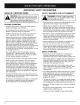
THE ENGINE EXHAUST FROM THIS PRODUCT CONTAINS CHEMICALS KNOWN TO THE STATE OF CALIFORNIA TO CAUSE CANCER, BIRTH DEFECTS OR OTHER REPRODUCTIVE HARM. NOTE: For users on U.S. Forest Land and in the states of California, Maine, Oregon and Washington. All U.S.
• IMPORTANT SAFETY INFORMATION READ ALL INSTRUCTIONS WARNING: When using the unit, you must[ follow the safety rules. For your own safety[ and that of bystanders, please read these [ instructions before operating the unit. [ Please keep the instructions for later use. BEFORE OPERATING • Read the instructions carefully. Be familiar with the controls and proper use of the unit. • Do not operate this unit when tired, ill or under the influence of alcohol, drugs or medication.
• Avoid accidental starting. Be in the starting position whenever pulling the starter rope. The operator and unit must be in a stable position while starting. Refer to Starting/Stopping Instructions. • Use the right tool. Only use this tool for its intended purpose. • Do not overreach. Always keep proper footing and balance. • Always hold the unit with both hands when operating. Keep a firm grip on both handles or grips. • Keep hands, face, and feet at a distance from all moving parts.
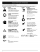
SAFETYAND INTERNATIONALSYMBOLS This operator's manual describes safety and international symbols and pictographs that may appear on this product. Read the operator's manual for complete safety, assembly, operating and maintenance and repair information. SYMBOL MEANING SYMBOL Indicates danger, warning, or • SAFETY ALERT SYMBOL caution. May be used in conjunction with other symbols or pictographs.
APPLICATIONS As a trimmer: • Cutting grass and light weeds • Edging • Decorative trimming around trees, fences, etc.
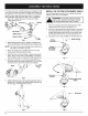
On some units, the J-handle may be pre-installed. In this case you must loosen screws and adjust the handle to fit the operator. Go to step 5 if the J-handle is pre-installed. INSTALLING . AND ADJUSTING INSTALL THE CUTTING ATTACHMENT Use the following instructions if the cutting attachment shield on your unit is not installed. THE J-HANDLE WARNING: To prevent serious personal I injury, never operate the trimmer without I Place the J-handle between the top and middle clamp pieces (Fig. 1).
OIL AND FUEL MIXING INSTRUCTIONS Old and/or improperly mixed fuel are the main reasons for the unit not running properly. Be sure to use fresh, clean unleaded fuel. Follow the instructions carefully for the proper fuel/oil mixture. Definition of Blended Fuels Today's fuels are often a blend of gasoline and oxygenates such as ethanol, methanol, or MTBE (ether). Alcohol-blended fuel absorbs water. As little as 1% water in the fuel can make fuel and oil separate. It forms acids when stored.
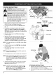
STARTING INSTRUCTIONS WARNING: Operate this unit only in a well. ventilated outdoor area. Carbon monoxide exhaust fumes can be lethal in a confined area. _i sure you areAvoid in the accidental starting position WARNING: starting,when Make pulling the starter rope (Fig, 9). To avoid serious injury, the operator and unit must be in a stable position while starting. Start/On % StoplOff (0) On/Off Mix gas with oil. Fill fuel tank with fuel/oil mixture. Refer to Oil and Fuel Mixing Instructions. 2.
OPERATING THE EZ-LINK TM SYSTEM 2. The EZ-LinM M system enables the use of these optional Add-Ons: Blower/Vacuum Cultivator .......................... NOTE: Aligning the release button with the guide recess will help installation (Fig. 10). BV720r .............................. While firmly holding the add-on, push it straight into the EZ-LinM M coupler (Fig. 11). GC720r Edger .................................. Release Button LE720r Hedge Trimmer .......................... Snow Thrower ......
HOLDING THE TRIMMER NOTE: Do not rest the Bump Head TM on the ground while the unit is running. WARNING: Always wear eye, hearing; foot and body protection to reduce the risk of injury when operating this unit. Before operating the unit, stand in the operating position (Fig. 13). Check for the following: CAUTION: Do not remove or alter the line cutting blade assembly. Excessive line length will make the clutch overheat. This may lead to serious personal injury or damage to the unit.
MAINTENANCE SCHEDULE NOTE: Maintenance, replacement, or repair of the emission control devices and system may be performed by any non-road engine repair establishment, individual or authorized service dealer. Perform these required maintenance procedures at the frequency stated in the table. These procedures should also be a part of any seasonal tune-up. NOTE: Some maintenance procedures may require special tools or skills.
. 4. Pull old line out of the line loading and line locking holes (Fig. 17 and 18). Insert a piece of trimming line straight into one of the two eyelets in the outer spool. Push it up through the line loading hole in the inner reel (Fig. 17). Do not bend the line when inserting it into the eyelet. 7. Repeat procedures 4-6 with the second piece of line. 8. Hold the outer spool. Wind the inner reel counterclockwise until approximately four (4) inches (102 mm) of line remain (Fig. 20).
. Pull the old inner reel with existing line from the outer spool. . 3. Insert the ends of the prewound inner reel line into the outer spool eyelets (Fig. 23). Push the new inner reel, arrow side up, into the outer spool. Remove any existing line from the inner reel before cleaning. Remove any debris or grass from the knob, spring, inner reel and foam seal. Wash the inner reel with warm soapy water (Fig. 25). Inner Reel Fig. 25 . . Fig.
AIR FILTER MAINTENANCE Removing the Air Filter/Muffler Cover WARNING:To avoid seriouspers0nalinjury, I always turn your trimmer off and allow it to coo before you c ean or service it. 1. Place the choke lever in the PARTIAL choke position (B). NOTE: The choke lever must be in the PARTIAL choke position (B) to remove the air filter/muffler cover. 2. Remove the four (4) screws securing the air filter/muffler cover (Fig. 27). Use a flat blade or T-20 Torx bit screwdriver. 3.
SPARK ARRESTOR 1. . . MAINTENANCE Remove air filter/muffler cover. Refer to Removing the Air Filter/Muffler Cover. Spark Arrestor Bolts_ Locate muffler front and the two (2) bolts securing it to the engine (Fig. 32). Remove the two (2) bolts using a fiatblade screwdriver or 5/16-inch socket or nut driver. Pull muffler off of the engine. \ Exhaust Gasket \ \ Turn muffler over to the back side and locate the exhaust gasket. Remove the muffler gasket from the muffler (Fig. 32).
CARBURETOR ADJUSTMENT The idle speed of the engine is adjustable through the air filter/muffler cover (Fig. 34). NOTE: Careless adjustments can seriously damage your unit. An authorized service dealer should make carburetor adjustments. Check Fuel Mixture Old and/or improperly mixed fuel is usually the reason for improper unit performance. Drain and refill the tank with fresh, properly-mixed fuel prior to making any adjustments. Refer to Oil and Fuel Information. Clean Air Filter 3.
CLEANING TRANSPORTING WARNING:To avoid serious personalinjury, always turn your trimmer off and allow it to coo before you c ean or service it. • Allow the engine to cool before transporting. ° Drain fuel from unit. • Tighten fuel cap before transporting. • Secure the unit while transporting. Use a small brush to clean off the outside of the unit. Do not use strong detergents.
CAUSE ACTION Empty fuel tank Fill fuel tank with properly mixed fuel Primer bulb wasn't pressed enough Press primer bulb fully and slowly 10 times Engine is flooded Squeeze the trigger and pull the starter rope Old or improperly mixed fuel Drain gas tank and add fresh fuel mixture Fouled spark plug Replace or clean the spark plug Plugged spark arrestor Clean or replace spark arrestor CAUSE ACTION Air filter is plugged Replace or clean the air filter Old or improperly mixed fuel Drain gas
Engine Type .......................................................................................................................................... Stroke ................................................................................................................................................... Air-Cooled, 2-Cycle 1.25 in. (31.75 mm.) Clutch Type .......................................................................................................................................................
EPA Emission Control Warranty Statement Your Warranty Rights and Obligations The Environmental Protection Agency and MTD SOUTHWEST INC (MTD) are pleased to explain the emission control system warranty on your 2002 and later small off-road engine. New small off-road engines must be designed, built and equipped to meet stringent anti-smog standards.
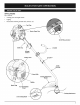
ENGINE PARTS 2-CYCLE - RYOBI 725r GAS TRIMMER PPN - 41ED725A034 Item 1 Part No.
BOOM & TRIMMER PARTS - RYOBI 725r 2-CYCLE GAS TRIMMER PPN - 41ED725A034 ®® Item 1 Part No.
MANUFACTURER'S LIMITED WARRANTY FOR: ® The limited warranty set forth below is given by MTD LLC ("MTD") with respect with new merchandise purchased and used in the United States, its possessions and territories. MTD warrants this product against defects in material and workmanship for a period of two (2) years commencing on the date of original purchase and will, at its option, repair or replace, free of charge, any part found to be defective in material or workmanship.