
Products owerns manual zero-turn riding mower L04


English Operating instructions
3
Disconnecting
• First disconnect the black cable
(–), and then the red cable (+).
• Remove the battery from the
appliance.
Connecting
• First connect the red cable (+),
and then the black cable (–).
Note!
The battery’s positive terminal is
marked with a plus sign (+).
The battery’s negative terminal is
marked with a minus sign (–).
Always make sure that the battery’s
vent line is correctly installed
(unobstructed downwards flow).
When a “maintenance-free/sealed”
battery (type 1) has been delivered
(battery without vent plug)
The battery is filled with battery acid
and sealed at the manufacturer’s.
The battery may have to be recharged.
To do so, see the section on servicing
the battery.
When an unfilled battery (type 2)
is delivered
(battery with vent plug)
• Remove the vent plug for the
battery cells.
• Slowly fill each cell with battery
acid until the level is 1 cm below
the filling aperture.
• Leave the battery for thirty
minutes so that the lead can
absorb the battery acid.
• Check the acid level,
if necessary top up the acid level.
• Before using the battery for the
first time, charge it with a battery
charger (max charging current 6 A
at 12 V) for 2–6 hours. After
charging, first disconnect the
mains plug to the charger and then
take out the battery (see also the
operating instructions for the
charger).
• Replace the vent plugs for the
battery cells.
• Remove the blank plug for the
battery’s vent. Attach the vent line
so that it runs downwards through
the appliance. Make sure that the
line is unobstructed!
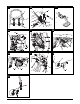
(Fig 4)
• Install the battery in the appliance.
• First connect the red cable (+),
and then the black cable (–).
• Refill the battery afterwards with
distilled water only.
(Check every two months.)
• Keep the battery clean.
Fuelling and checking/topping up
the oil level
Fill the machine with petrol and oil as
described in the provided engine
handbook.
Note! The engine may have been
filled with oil at the manufacturer’s –
please check and if necessary refill.
(The oil level must lie between the
Full/Max and Add/Min marks.) Never
fill the petrol tank to overflowing, but
until the level reaches 1 cm below the
filler’s lower edge.
Seal the petrol tank securely.
Risk of asphyxiation from carbon
monoxide
Run the IC engine outdoors only.
Risk of explosion and fire
Fuel/petrol vapours are explosive,
and fuel is highly flammable. Fill the
engine with fuel before turning the
ignition. Keep the petrol tank closed
when the engine is running or is still
hot. Refill with fuel only when the
engine has been switched OFF and has
cooled down. Avoid naked flames and
sparking, and do not smoke. Fuel the
appliance outdoors only. Do not start
the engine when fuel has overflowed.
Remove the appliance from the fuel-
contaminated site and wait until the
fuel has completely evaporated.
To prevent the risk of fire, please keep
the following parts free of grass and
leaking oil: engine, exhaust, battery,
fuel tank.
Removing the transport safety plate
on the cutters
Fig 3
Push the deflector back slightly, and
remove the transport safety plate.
The deflector closes automatically.
Checking the tyre pressure
Pressurise the front tyres to approx.
2.3 bar and the rear tyres to approx.
0.8 bar. See also the manufacturer’s
recommendation on the tyre walls.
Controls and indicators
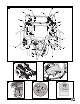
Fig 1
A. cutting height segment
B. cutting height lever
C. right and left drive control lever
D. ignition lock
E. PTO switch
F. gear release for hydrostatic drive
(not shown)
G. cup holder
H. storage tray
J. seat adjuster (not shown)
K. tank cap
L. composite indicator (optional)
M. accelerator lever
N. control lever for the locking brake
Cutting height segment (A)
Fig 1
Each notch corresponds to approx.
1.25 cm:
lowest position: approx. 4 cm
highest position: approx. 10 cm
Cutting height lever (B)
Fig 1
This lever adjusts the cutting height
and is locked in place by the
respective recesses.
Right and left drive control lever
(C)
Fig 1
These levers change the drive
direction, control the speed, and stop
the appliance (see detailed description
in the section “Operation”).
Note!
Before the engine can be
started, both control levers must be in
the outer Neutral recesses.
Ignition lock (D)
Fig 5
The ignition lock has three settings.
1. O/ = OFF/engine stop.
2. ON/ = electrical system
switched ON or engine run mode.
3. Start/ = starter confirmation:
when the engine is running,
release the key.