Safe Operation Practices • Set-Up • Operation • Maintenance • Service • Troubleshooting • Warranty L Hydrostatic Lawn Tractor m Model Series 790 MTD LLC, P.O. BOX 361131 CLEVELAND, OHiO 44136-0019 PrintedIn USA FormNo.
1 ToTheOwner ThankYou Thank you for purchasing a lawn tractor manufactured by If you have any problems MTD LLC. It was carefully engineered to provide excellent performance when properly operated and maintained. Please read this entire manual It instructs prior to operating your machine. persons who will operate address and mailing the equipment.
2 ImportantSafeOperationPractices WARNING! This symbol could endanger points the personal all instructions safety and/or in this manual with these instructions out important before property attempting may result in personal When you see this symbol. safety instructions of yourself to operate which, if not followed, and others. this machine. Read and follow Failure to comply injury.
12. Amissing ordamaged discharge cover cancause blade Slope Operation contact orthrown object injuries. Slopes are a major factor related to loss of control and tip-over 13. Stoptheblade(s) whencrossing gravel drives, walks, or accidents which can result in severe injury or death. All slopes roads andwhilenotcutting grass. require extra caution. If you cannot back up the slope or if you feel uneasy on it, do not mow it. 14. Watch fortrafficwhenoperating nearorcrossing roadways.
Children 1. Service Tragic accidents presence ca n occur if the operator of children. is not alert to the Children are often attracted to the machine and the mowing activity. They do not understand the dangers. Never assume that children will remain where SafeHandling of Gasoline: 1. Keep children watchful out of the mowing care of a responsible personal area and in yourself adult other than the Be alert and turn machine off if a child enters the area. c.
3. 4. Periodically stop within operating approximately the blade disengagement (5) five seconds after control. If the blades frequently operation. as it is subjected Check the blade(s) and engine for proper tightness. may lead to improper to wear Adjust and service as required. mounting bolts at frequent Also, visually inspect equipment performance blade(s) Replace manufacturer's (O.E.M.) blade(s) only, listed in this manual.
Safety Symbols This page depicts and describes safety symbols that may appear machine before attempting to assemble and operate. on this product. Read, understand, and follow all instructions on the READ THE OPERATOR'S MANUAL(S) Read, understand, assemble and follow all instructions in the manual(s) before attempting to and operate DANGER-- ROTATING BLADES Never carry passengers. Never carry children, even with the blades off.
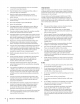
co or a corner of a building... I I -4 6 Z | I ,_ I I I | Z ' /:Oldo,_ O ' ' or a fence post ', " .- 22 diine 6 .I Z ' "o a 15Oslope -4 I I 15 ° Usethis page as a guide to determine slopes where you may not operate safely. WARNING! Do not operate (a rise of approximately mowers up and down your lawn mower on such slopes. Do not mow on inclines 2-1/2 feet every 10 feet). A riding mower slopes, never across the face of slopes.
3 Assembly & Set-Up Shipping BraceRemoval TractorSet-lip NOTE:This Operators Manual covers a range of product specifications for various models. Characteristics and features discussed and/or illustrated in this manual may not be applicable to all models.
To install: Attaching The Steering Wheel If the steering hardware wheel for your tractor did not come attached, for attaching it has been packed within wheel, beneath the steering wheel cap. Carefully steering wheel cap and remove the hardware. I. With the wheels place the steering 2. of the tractor pointing Place the washer (with the cupped steering 1. Carefully 2. Remove the four screws from the underside pry offthe forward, hood forward.
separate tractor. MukhPlug(ifequipped) On tractor within models the cutting so equipped, a mulch deck's discharge plug can be found opening. NOTE: Refer to Mulching in the "Operation" manual for more detailed information. If you'd prefer to operate the cutting Engine Operator/Owner Read instructions deck without of this packed with your IMPORTANT: Your tractor is shipped with motor oil in the engine. However, you MUST check the oil level before operating. section Manual carefully.
4 Controls and Features Throttle/Choke Lever Ignition Switch Module Speed Control Lever PTO (Blade Engage) Lever ,,. Deck Lift Lever - j Figure 4=1 Lawn Tractor controls i_ and features are illustrated before attempting to operate WARNING! Read and follow injury. in Fig 4-1 and described on the following pages. this machine.
ThrottleControl Lever The throttle control lever is located on the right side of the tractor's dash panel. This lever controls the speed of the engine and, on some models, when pushed all the way forward, choke control also. When set in a given position, maintain a uniform Off the the throttle will engine speed. See Fig. 4-2. FAST ® Off SLOW SLOW Figure 4-2 iMPORTANT: When Start operating the tractor engaged, be certain that the throttle (rabbit) position.
To stop the engine, OFF position. turn the ignition key counterclockwise to the See Fig. 4-3B. Ignition Switch Module To start the engine, insert the key into the ignition switch and turn clockwise to the START position. Release the key into the NORMAL MOWING MODE position once the engine has fired. The headlights will be activated in the Normal (and Reverse Caution SPEED Modes). To stop the engine, OFF position. turn the ignition key counterclockwise to the See Fig. 4-3C. unattended.
Operation Models with ReverseCaution Mode With the ignition the engine TO AVOID SERIOUS OR DEATH key in the NORMAL MOWING position, will automatically shut off if the PTO (blade engage) lever is moved into the engaged the speed control in Reverse. INJURY • GOUP AND DOWNSLOPES,NOT ACROSS. (ON) position with interlock system WARNING! Do designed • AVOIDSUDDENTURNS. is malfunctioning. This system was not operate the tractor if the for your safety a nd protection.
4. Once activated (indicator light ON), the tractor driven in reverse with the cutting 5. can be blades (PTO) engaged. Always look down and behind before and while make sure no children are around. 6. After resuming forward NORMAL MOWING IMPORTANT: The activated motion, backing to 3. Engage the tractor's 4. Activate 5. Turn the ignition return the key to the position. key clockwise to the START position.
4. 5. The lawn tractor is brought to a stop by depressing the Models without ReverseCautionMode: brake pedal. The PTO (blade engage) lever must be in the disengaged Set the parking brake by fully depressing the brake pedal and keeping it depressed while placing the parking brake position lever in the ON position. the parking Release the brake pedal to allow brake to engage. when starting if the operator on page 15.
Mulching MovingTheTractorManually Select models come equipped with a mulch kit which incorporates special blades, already standard on the tractor, in a process of recirculating grass clippings repeatedly beneath the cutting deck. The ultra-fine clippings are then forced back into the lawn where they act as a natural fertilizer. Observe the following Yourtractor'stransmissionis equippedwith a hydrostaticrelief valvefor occasionswhenit is necessaryto movethe tractor manually.
6 Maintenance& Adjustments Maintenance NOTE: Refer to the Engine Operator/Owner your unit for information WARNING! Before performing any maintenance or repairs, disengage PTO, move shift lever into neutral position, set parking brake, stop engine and remove key to prevent unintended starting. viscosity of motor regarding Manual the quantity packed with and proper oil.
CleaningBattery Clean the battery with a baking battery DeckWash System TM by removing it from the tractor soda and water solution. terminals and washing If necessary, scrape the with a wire brush to remove deposits. terminals and exposed prevent corrosion.
IMPORTANT: After cleaning your deck with the Deck Wash System return to the operator's position and engage the PTO. Keep the cutting deck running for a minimum of two minutes, allowing the underside of the cutting deck to thoroughly dry. TM, Sideto Side If the cutting adjustment 1. Adjustments deck appears to be mowing can be performed.
MaintenanceSchedule Before Eachuse Every lOHours Every 25 Hours Every 50 Hours Every 100Hours Prior to Storing ,/ CleanHood/DashLouvers CheckEngineOil Level V// CheckAir Filter for Dirty, Looseor DamagedParts V/" ,/ V// CleanandRe-oilAir Filter'sFoamPre-cieaner V/" ReplaceAir Filter Element V/ ChangeEngineOiland ReplaceOil Filter V/ CleanBattery Terminals _" _" LubeFrontAxlesand Rims _" _" CleanEngineCoolingFins _" _" LubePedalPivot Points _" _" CheckSparkPlug Condition&Gap _
7 Service Cutting Deck Removal NOTE: Models equipped with a 38-inch pulley. Models equipped deck idler pulleys. with a 42- and 46-inch To remove the cutting 1. deck, proceed deck have one deck idler deck have two as follows: Place the PTO (Blade Engage) lever in the disengaged position and engage the parking (OFF) brake. 2. Lower the deck by moving the deck lift lever into the bottom notch on the right fender. 3.
f 4. Make the final connection tractor, on the engine away from the battery. Attach block of the to a unpainted part to assure a good connection. iiiii_ii_iiii_i_iii_i_il i_i_iii_i_iiiiiiiii_i_iiii_i:ii%_iiiil // vehicle (i.e. car, truck), do NOT start the vehicle's AUTION: the jumper is installed on a engine when Ifjump starting battery your tractor. _ \ 5. Start the tractor this manual). (as instructed in the Operation 6.
Cutting Blades WARNING! ignition Shut the engine off and remove key before removing the cutting blade(s) for sharpening or replacement. Protect your hands by using heavy gloves when grasping the blade. WARNING! Periodically inspect the blade and/or spindle for cracks or damage, struck a foreign until damaged To remove the blades, proceed 1. after you've as follows. Remove the deck from beneath Cutting especially object. Do not operate the machine components are replaced. Deck Removal \\ t
4. On the 42-inch deck only, loosen but do not remove, the 5. idler pulley nuts. This will enable the belt to be easily removed Remove the deck belt from around all pulleys, including the deck idler pulley. from the idler pulleys. See Fig. 7-7. 6. Route the new belt as shown in and Fig. 7-8, 7-9 or 7-10, depending 7. Idler pulleys Remount on your specific sized deck. the belt guards removed earlier.
42-inch Deck Engine Pulley © Deck Idler Pulleys J Figure 7-9 46-inch Deck © © Belt Cover Idler Pulleys Figure 7=10 SECTION 7 -- SERVICE 27
Troubleshooting Problem Cause Engine fails to start Remedy PTO/Blade engaged. 1. Place knob (or lever) in disengaged (OFF) position. 2. Spark plug wire disconnected. 2. Connect wire to spark plug. 3. Fuel tankempty, 3. Fill tank with clean, fresh (less than 30 days old) gas. or stale fuel. 4. Choke notactivated. 4. Place the throttle 5. Faulty spark plug. 5. Clean, adjust gap or replace plug. 6. Blocked fuel line. 6. Clean fuel line and replace fuel filter. 7. Engine flooded. 7.
9 Replacement Parts NOTE:This and/or Operators illustrated Manual.
Attachments & Accessories 1 Thefollowingattachmentsand accessoriesare compatiblefor ModelSeries700 HydrostaticLawnTractors.See the retailerfrom which youpurchasedyourtractor,an authorizedMTDService Dealeror phone (800) 800-7310for informationregardingpriceand availability. _[j attachments(e.g. tilleror plow). Useof this type of equipmentWILL voidthe tractor'swarranty.
CALIFORNIA EMISSION CONTROL WARRANTY STATEMENT YOUR WARRANTY RIGHTS AND OBLIGATIONS The CaliforniaAir ResourcesBoardandMTDConsumerGroupInc are pleasedto explainthe evaporativeemissioncontrolsystemwarrantyon your2007 lawn mower.In California,new lawnmowersmust be designed,built and equippedto meetthe State'sstringentanti-smogstandards.MTDConsumerGroupInc must warrantthe EECSon yourlawn mowerfor the periodof time listed below providedthere has beenno abuse, neglector impropermaintenanceof yourlawn mower.
MANUFACTURER'S LiMiTED WARRANTY The limited warranty set forth below is given by MTD LLC with respect to new merchandise purchased and used in the United States and/or its territories and possessions, and by MTD Products Limited with respect to new merchandise purchased and used in Canadaand/ or its territories and possessions (either entity respectively, "MTD").