Safe Operation Practices • Set-Up • Operation • Maintenance • Service • Troubleshooting 's • Warranty L Rear Tine Tiller m Moclel Series 410 MTD LLC, P.O. BOX 361131 CLEVELAND, OHiO 44136-0019 PrintedIn USA FormNo.
1 ToTheOwner ThankYou Thank you for purchasing a Garden Tiller manufactured by This product has met the rigid safety standards Power Equipment Institute and an independent MTD LLC. It was carefully engineered to provide excellent performance when properly operated and maintained. Please read this entire It instructs maintain persons manual prior to operating you how to safely and easily set up, operate your machine. laboratory.
2 importantSafeOperationPractices WARNING! This symbol could endanger all instructions points the personal safety and/or in this manual with these instructions out important before property attempting may result in personal When you see this symbol. safety instructions of yourself to operate which, if not followed, and others. Read and follow this machine. Failure to comply injury.
When practical, e_ equipment 11. After striking dispenser nozzle. 12. Keep the nozzle in contact with the rim of the fuel tank or container at all times until fueling opening complete. Do not use a nozzle lock-open Extinguish all cigarettes, g. Never remove Disengage all clutch levers (if fitted) is handles). device. before unclogging inspections. cigars, pipes and other to cool at least two Never over fill fuel tank. Fill tank to no more than 1/2 bottom 15.
9. If the fuel tank has to be drained, 10. Observe proper etc. to protect disposal do this outdoors. laws and regulations AverageUsefulLife for gas, oil, the environment. EPA emission are certified regulations hours of operation. to comply with California and federal for SORE (Small Off Road Equipment) are certified to operate on regular may include the following emission to the Consumer Products Safety Commission (CPSC) and the U.S.
3 Assembly& Set-Up Contents of Carton OneTiller One Depth Stake One Handlebar Assembly One Shift Rod One Operator's Manual One Engine Operator's Manual Assembly Depth Stake UnpackingInstructions NOTE: References to the right or left side of the tiller are determined behind from the machine in the operating position. 1. 1. plug wire and Before groundassembly, it against disconnect the engine the to spark ARNING! prevent unintended starting.
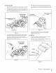
HandlebarAssembly 1. Remove the handle adjustment bracket, 2. 4. shoulder crank, flange bolt, and lock nut from slots in the pivot bracket. and install 3-4. bracket. Place the handle assembly into position in the handle pivot bracket by lining up the upper holes in the handle with the of the flange nut retainer over the flange nut securing nut, retainer the pivot Place the hex opening bracket the handle adjustment the lock nut on the lower shoulder crank bolt. See Fig. f See Fig. 3-2.
3_ Insert the end of the gear shift rod through the opening in the top of the shift cover and into the shift bracket. First, secure the rubber washer then the flat washer and cotter pin. See Fig. 3-6. 4_ Pull the cable upwards to obtain slack and hook the Zconnector at the end of the cable into the bracket on the clutch control (beneath the handle panel). Tighten against the cable bracket. See Fig. 3-8. the nut r Shift Rod Hex Nut _ Opening Lock Washer Slot il Cable Bracket k. j Figure 3=6 4.
Set-Up Tires The tires on your tiller may be over-inflated purposes. Reduce the tire pressure before for shipping operating. The recommended operating tire pressure is approximately 14 p.s.i. on 14 inch tires. Check the sidewall of tire for tire manufacturer's recommended i_ pressure. circumstances is 30 p.s.i. Equal tire pressure should WARNING! be maintained Maximum on both tires.
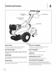
4 Controls and Features Clutch Handle Handle Adjustment Crank j Depth Stake J Figure 44 EngineControls See the separate information ChokeLever(if equipped) Engine Operator's and functions Manual The choke lever is used to enrich the fuel mixture for additional of the engine controls. carburetor GearSelection Handle The gear selection handle is located on the front of the handle The primer The depth The clutch handle is located beneath the handle.
Operation When using the tiller for the first time, use the second Starting the Engine instructions WARNING! this manual i_ll NOTE:When pushing adjustment 5-1. and warnings on theand machine Read, understand, follow and all in before operating. the machine hear a ratcheting-gear This is normal. with the engine sound coming F 2. Place the throttle equipped, See Fig. off, you will from the tiller's chain case. Use this position _ort Position pass...
5. For further depth, raise the depth stake and side shields and also make one or two more passes over the area. 6. When tilling loose soil, the depth highest position give the deepest highest 7. stake may be raised to its by using the bottom adjustment hole to tilling depth. Raise the side shields to the position. To transport the tiller, lower the depth top adjustment stake by using the hole. Operatingthe Tiller 1. Select the depth stake setting. 2.
6 Maintenance& Adjustments Lubrication ground it against the engine performing ARNING! Disconnect the before spark plug wire and any maintenance or repairs. _ Transmission The transmission Maintenance requires is pre-lubricated no checking and sealed at the factory. unless the transmission Refer to the separate Engine Operator's maintenance instructions. Manual half to it. This grease can be obtained for engine dealer by ordering part number at your nearest authorized 737-0300A.
Off-SeasonStorage If the tiller will not be used for a period longer than 30 days, the following steps should be taken to prepare the tiller for storage. Clean the exterior thoroughly. lubrication of the engine and the entire tiller Lubricate the tiller as described instructions. in the The use of a pressure washer to clean your tiller is not recommended. The washer may cause damage to electric components, spindles, pulleys, bearings or the engine.
7 Service Belt Replacement Your tiller has been engineered with a belt designed for long life and optimal performance. It should never be replaced with a non-OEM belt. Order all belts through an authorized service dealer or by contacting Customer Support as instructed on page 2. Refer to Fig. 7-1 for the following steps. Engine PuJ Bolt Figure 7-1 1. Disconnect and ground the spark plug wire against the engine. 2.
Troubleshooting Problem Engine fails to start Engine runs erratic Cause 1, Fuel tankempty, Remedy or stale fuel. 1. Fill tank with clean, fresh gasoline. 2. Throttle control lever not in correct starting position (if equipped). 2. Move throttle 3. Blocked fuel line. 3. Clean fuel line, 4. Dirty air cleaner. 4. Refer to the Engine Operator's 5. Choke not in ON posit=on, 5. Move switch to ON position. 6. Spark plug wire disconnected. 6, Connect wire to spark plug, 7. Faulty spark plug, 7.
9 ReplacementParts Component Phone (800) 800-7310 serial number or (330) 220-4683 ready). Parts Manual [ to order replacement downloads are also available Part Number and Description 754-0434 V-Belt, I/2x 51.
1
SECTION11 = NOTES 19
MANUFACTURER'S LiMiTED WARRANTY The limited warranty set forth below is given by MTD LLC with respect to new merchandise purchased and used in the United States and/or its territories and possessions, and by MTD Products Limited with respect to new merchandise purchased and used in Canadaand/ or its territories and possessions (either entity respectively, "MTD").