Safe Operation Practices • Set-Up • Operation • Maintenance • Service • Troubleshooting • Warranty operator’s manual Model Series 760-770 Lawn Tractor WARNING READ AND FOLLOW ALL SAFETY RULES AND INSTRUCTIONS IN THIS MANUAL BEFORE ATTEMPTING TO OPERATE THIS MACHINE. FAILURE TO COMPLY WITH THESE INSTRUCTIONS MAY RESULT IN PERSONAL INJURY. P. O. Box 1386, 97 Kent Avenue, KITCHENER, ONTARIO, CANADA N2G 4J1 Printed In USA 769-05456B 11.30.
1 To The Owner Thank You Thank you for purchasing your new equipment. It was carefully engineered to provide excellent performance when properly operated and maintained. The manufacturer reserves the right to change product specifications, designs and equipment without notice and without incurring obligation. Please read this entire manual prior to operating the equipment. It instructs you how to safely and easily set up, operate and maintain your machine.
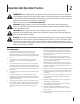
Important Safe Operation Practices 2 WARNING: This symbol points out important safety instructions which, if not followed, could endanger the personal safety and/or property of yourself and others. Read and follow all instructions in this manual before attempting to operate this machine. Failure to comply with these instructions may result in personal injury. When you see this symbol.
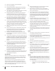
16. Mow only in daylight or good artificial light. Do: 17. Never carry passengers. 1. 18. Disengage blade(s) before shifting into reverse. Back up slowly. Always look down and behind before and while backing to avoid a back-over accident. Mow up and down slopes, not across. Exercise extreme caution when changing direction on slopes. 2. Watch for holes, ruts, bumps, rocks, or other hidden objects. Uneven terrain could overturn the machine. Tall grass can hide obstacles. 3. Use slow speed.
2. b. Be alert and turn machine off if a child enters the area. c. Before and while backing, look behind and down for small children. d. Never carry children, even with the blade(s) shut off. They may fall off and be seriously injured or interfere with safe machine operation. e. Use extreme care when approaching blind corners, doorways, shrubs, trees or other objects that may block your vision of a child who may run into the path of the machine. f.
. Mower blades are sharp. Wrap the blade or wear gloves, and use extra caution when servicing them. 7. Keep all nuts, bolts, and screws tight to be sure the equipment is in safe working condition. 8. Never tamper with the safety interlock system or other safety devices. Check their proper operation regularly. 9. After striking a foreign object, stop the engine, disconnect the spark plug wire(s) and ground against the engine. Thoroughly inspect the machine for any damage.
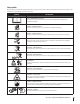
Safety Symbols This page depicts and describes safety symbols that may appear on this product. Read, understand, and follow all instructions on the machine before attempting to assemble and operate. Symbol Description READ THE OPERATOR’S MANUAL(S) Read, understand, and follow all instructions in the manual(s) before attempting to assemble and operate DANGER— ROTATING BLADES Never carry passengers. Never carry children, even with the blades off.
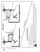
Section 2 — Important Safe Operation Practices Figure 1 line Figure 2 (TOO STEEP) 15° Slope WARNING! Slopes are a major factor related to tip-over and roll-over accidents which can result in severe injury or death. Do not operate machine on slopes in excess of 15 degrees. All slopes require extra caution. If you cannot back up the slope or if you feel uneasy on it, do not mow it. Always mow up and down slopes, never across the face of slopes. To check the slope, proceed as follows: 1.
3 Assembly & Set-Up Tractor Set-Up NOTE: This Operators Manual covers a range of product specifications for various models. Characteristics and features discussed and/or illustrated in this manual may not be applicable to all models. The manufacturer reserves the right to change product specifications, designs and equipment without notice and without incurring obligation.
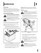
Attaching The Steering Wheel Attaching The Seat If the steering wheel for your tractor did not come attached, the hardware for attaching it has been packed within the steering wheel, beneath the steering wheel cap. Carefully pry off the steering wheel cap and remove the hardware. If the seat for your tractor was not attached at the factory, follow the applicable instructions below to attach it. NOTE: There are two different syles of steering wheel caps. Styles vary by model. 1.
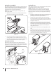
Mulch Plug (optional) Setting the Deck Gauge Wheels (if so equipped) Note: See the Attachments & Accessories section if you would like information regarding adding a mulching system for your model of tractor. Move the tractor on a firm and level surface, preferably pavement, and proceed as follows 1. Select the height position of the cutting deck by placing the deck lift lever in the normally desired mowing height setting (any of the six different cutting height notches on the right fender). 2.
4 Controls and Features Throttle/Choke Lever Speed Control & Parking Brake Lever Ignition Switch Module Clutch/Brake Pedal Ammeter (On some models) Shift Lever Deck Lift Lever PTO (Blade Engage) Lever Figure 4-1 Lawn Tractor controls and features are illustrated in Fig 4-1 and described on the following pages. WARNING! Read and follow all safety rules and instructions in this manual, including the entire Operation section, before attempting to operate this machine.
Throttle Control Lever The throttle control lever is located on the left side of the tractor’s dash panel. This lever controls the speed of the engine and, on some models, when pushed all the way forward, the choke control also. When set in a given position, the throttle will maintain a uniform engine speed. See Fig. 4-2.
To stop the engine, turn the ignition key counterclockwise to the OFF position. See Fig. 4-3B. Ignition Switch Module To start the engine, insert the key into the ignition switch and turn clockwise to the START position. Release the key into the NORMAL MOWING MODE position once the engine has fired. The headlights will be activated in the Normal (and Reverse Caution Modes). To stop the engine, turn the ignition key counterclockwise to the OFF position. See Fig. 4-3C.
5 Operation Models with Reverse Caution Mode • With the ignition key in the NORMAL MOWING position, the engine will automatically shut off if the PTO (Blade Engage) lever is moved into the engaged (ON) position with the shift lever in Reverse. WARNING! Do not operate the tractor if the interlock system is malfunctioning. This system was designed for your safety and protection.
4. Once activated (indicator light ON), the tractor can be driven in reverse with the cutting blades (PTO) engaged. 5. Always look down and behind before and while backing to make sure no children are around. 6. After resuming forward motion, return the key to the NORMAL MOWING position. IMPORTANT: The REVERSE CAUTION MODE will remain activated until: a. The key is placed in either the NORMAL MOWING position or STOP position. b.
Driving The Tractor WARNING! Avoid sudden starts, excessive speed and sudden stops. WARNING! Do not leave the seat of the tractor without first placing the PTO (Blade Engage) lever in the disengaged (OFF) position, depressing the brake pedal and engaging the parking brake. If leaving the tractor unattended, also turn the ignition key off and remove the key. 6. Place speed control lever in desired position. 7. Place shift lever in either FORWARD or REVERSE, and follow normal operating procedures.
Mowing WARNING! To help avoid blade contact or a thrown object injury, keep bystanders, helpers, children and pets at least 75 feet from the machine while it is in operation. Stop machine if anyone enters the area. The following information will be helpful when using the cutting deck with your tractor: WARNING! Plan your mowing pattern to avoid discharge of materials toward roads, sidewalks, bystanders and the like.
6 Maintenance & Adjustments Maintenance Spark Plug WARNING! Before performing any maintenance or repairs, disengage PTO, move shift lever into neutral position, set parking brake, stop engine and remove key to prevent unintended starting. The spark plug should be cleaned and the gap reset once a season. Spark plug replacement is recommended at the start of each mowing season. Refer to the Engine Operator/Owner Manual for correct plug type and gap specifications.
Battery Failures Deck Wash System™ Some common causes for battery failure are: If your tractor’s deck is equipped with a water port on its surface as part of its Deck Wash System™, follow these instructions to utilize this feature. • Incorrect initial activation • Overcharging • Freezing • Undercharging Use the Deck Wash System™ to rinse grass clippings from the deck’s underside and prevent the buildup of corrosive chemicals.
IMPORTANT: After cleaning your deck with the Deck Wash System™ , return to the operator’s position and engage the PTO. Keep the cutting deck running for a minimum of two minutes, allowing the underside of the cutting deck to thoroughly dry. Side to Side Adjustments 4. With the tractor parked on a firm, level surface, place the deck lift lever in the top notch (highest position) and rotate both blades so that they are perpendicular with the tractor. 5.
Maintenance Schedule Before Each use Clean Hood/Dash Louvers Check Engine Oil Level Check Air Filter for Dirty, Loose or Damaged Parts P P Every 10 Hours Every 25 Hours Every 50 Hours P P P P Replace Air Filter Element P Change Engine Oil and Replace Oil Filter P P P Lube Front Axles and Rims Clean Engine Cooling Fins Lube Pedal Pivot Points Check Spark Plug Condition & Gap Replace Fuel Filter Prior to Storing P Clean and Re-oil Air Filter’s Foam Pre-cleaner Clean Battery Terminals Every 10
7 Service Cutting Deck Removal 5. NOTE: Models equipped with a 38-inch deck have one deck idler pulley. Models equipped with a 42- and 46-inch deck have two deck idler pulleys. To remove the cutting deck, proceed as follows: 1. Place the PTO (Blade Engage) lever in the disengaged (OFF) position and engage the parking brake. 2. Lower the deck by moving the deck lift lever into the bottom notch on the right fender. 3.
7. On 46” Decks: Looking at the cutting deck from the left side of the tractor, locate the deck support pin on the rear left side of the deck. Pull the deck support pin outward to release the deck from the deck lift arm. See Fig. 7-4. Repeat the above steps on the tractor’s right side. 9. Carefully remove the PTO cable from the rear of the cutting deck by removing the hair pin clip which secures it. Remove the spring from the deck idler bracket. See Fig.
Jump Starting Cutting Blades WARNING! Never jump start a damaged or frozen battery. Be certain the vehicles do not touch, and ignitions are off. Do not allow cable clamps to touch. 1. WARNING! Shut the engine off and remove ignition key before removing the cutting blade(s) for sharpening or replacement. Protect your hands by using heavy gloves when grasping the blade. Connect positive (+) cable to positive post (+) of your tractor’s discharged battery. 2.
5. Route the new belt as shown in Fig. 7-10. 6. Remount the belt guards removed earlier. For 42” & 46” Decks To change or replace the deck belt on your tractor, proceed as follows: 1. Remove the deck as instructed earlier in this section. 2. Remove the belt covers by removing the hex screws that fasten them to the deck. See Fig. 7-9.
38-Inch Deck Engine Pulley Idler Bracket Deck Idler Pulley Figure 7-10 42 & 46-Inch Deck Figure 7-11 Section 7 — Service 27
8 Troubleshooting Problem Engine fails to start Remedy 1. Place knob (or lever) in disengaged (OFF) position. 2. Spark plug wire disconnected. 2. Connect wire to spark plug. 3. Fuel tank empty, or stale fuel. 3. Fill tank with clean, fresh (less than 30 days old) gas. 4. Choke not activated. 4. Place the throttle control in CHOKE position. 5. Faulty spark plug. 5. Clean, adjust gap or replace plug. 6. Blocked fuel line. 6. Clean fuel line and replace fuel filter. 7. Engine flooded. 7.
9 Attachments & Accessories The following attachments and accessories are compatible with your lawn tractor. See your authorized dealer or the retailer from which you purchased your tractor for information regarding price and availability. CAUTION: Your lawn tractor is NOT designed for use with any type of ground-engaging attachments (e.g. tiller or moldboard plow). Use of this type of equipment WILL void the tractor’s warranty.
10 Replacement Parts DESCRIPTION PART NO. Drive Belt (Mowing Deck) 38” Deck 954-04062 Deck Blade (38” Deck) 942-0610A Deck Spindle (38” Deck) 918-04474A Battery 925-1707D Tire (Front) 13 x 5 x 6 Round Shoulder 734-04372 Tire (Front) 15 x 6 x 6 Round Shoulder 734-04240A Tire (Front) 15 x 6 x 6 Square Shoulder 734-1731 Tire (Rear) 18 x 6.
11 TWO YEAR LIMITED WARRANTY The limited warranty set forth below is given by MTD Products Limited with respect to new merchandise purchased and used in Canada and/or its territories and possessions (either entity respectively, “MTD”).
FEDERAL and/or CALIFORNIA EMISSION CONTROL WARRANTY STATEMENT YOUR WARRANTY RIGHTS AND OBLIGATIONS MTD Consumer Group Inc, the United States Environmental Protection Agency (EPA), and, for those products certified for sale in the state of California, the California Air Resources Board (CARB) are pleased to explain the emission (evaporative and/or exhaust) control system (ECS) warranty on your outdoor 2006 and later small off-road spark-ignited engine and equipment (outdoor equipment engine) In California, n
6. The outdoor equipment engine owner will not be charged for diagnostic labor that is directly associated with diagnosis of a defective, emission-related warranted part, provided that such diagnostic work is performed at a warranty station. 7. MTD Consumer Group Inc is liable for damages to other engine or equipment components proximately caused by a failure under warranty of any warranted part. 8.
Notes 34
Safe Operation Practices • Set-Up • Operation • Maintenance • Troubleshooting • Warranty OPERATOR’S MANUAL 420 cc OHV Vertical Shaft Engine WARNING READ AND FOLLOW ALL SAFETY RULES AND INSTRUCTIONS IN THIS MANUAL BEFORE ATTEMPTING TO OPERATE THIS MACHINE. FAILURE TO COMPLY WITH THESE INSTRUCTIONS MAY RESULT IN PERSONAL INJURY. MTD Products Ltd., P. O. Box 1386, KITCHENER, ONTARIO N2G 4J1 Printed In USA 769-09539 11.18.
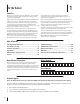
1 To The Owner Thank You This Operator’s Manual is an important part of your new engine. It will help you prepare and maintain the engine for the best performance. Please read and understand the contents before operating the engine. Table of Contents Safe Operation Practices......................................... 3 Maintenance & Adjustments..................................10 Safety Labels............................................................ 5 Troubleshooting......................................
Important Safe Operation Practices 2 WARNING! This symbol points out important safety instructions which, if not followed, could endanger the personal safety and/or property of yourself and others. Read and follow all instructions in this manual before attempting to operate the equipment. Failure to comply with these instructions may result in personal injury. When you see this symbol.
Do not overfill fuel tank. Fill tank to full as indicated by the fuel level indicator installed inside of the fuel tank. Do not over-fill to allow space for fuel expansion. On some models, a fuel level indicator may NOT be present, in this instance, fill the tank no more than 1/2 inch below the bottom of the filler neck to allow space for fuel expansion. Maintenance & Storage 8. 7. 1. Keep the engine in safe working order 2. Allow the engine to cool at least five minutes before storing.
Safety Symbols This page depicts and describes safety symbols that may appear on this product. Read, understand, and follow all instructions on the machine before attempting to assemble and operate. Symbol Description READ THE OPERATOR’S MANUAL(S) Read, understand, and follow all instructions in the manual(s) before attempting to assemble and operate WARNING—GASOLINE IS FLAMMABLE Allow the engine to cool at least two minutes before refueling.
3 Set-Up Gas & Oil Checking Oil Level NOTE: The engine is shipped without gasoline and with motor oil in the engine. However, you MUST check the oil level before operating. Be careful not to overfill. Running the engine with insufficient oil can cause serious engine damage and void the engine warranty. NOTE: Be sure to check the oil while on a level surface with the engine stopped. WARNING! Always keep hands and feet clear of 1. Remove the oil filler cap/dipstick and wipe the dipstick clean. 2.
Fuel Requirements Adding Fuel WARNING! An adult should fuel this engine. NEVER allow children to refuel the engine. Gasoline (fuel) vapors are highly flammable and can explode. Fuel vapors can spread and be ignited by a spark or flame many feet away from engine.
4 Controls and Features Air Cleaner Finger Guard Oil Fill Cap Electric Starter Spark Plug Oil Drain Muffler Fuel Filter Carburetor Oil Filter Figure 4-1 Throttle/Choke Control Oil Fill Cap The throttle/choke control is located on the mower and is used to aid in starting/stopping the engine and adjusting engine speeds. Refer to the Controls and Features section of the mower manual for more information regarding this control. Remove the oil fill cap to check the oil level and add oil.
5 Operation Pre-Operation Check Run Position The engine is shipped without gasoline and with oil in the engine. See the Set-Up Section of this manual for instructions on adding gasoline and checking oil. Stop Position Starting the Engine 1. Release all controls on the mower. 2. Move the gear shift lever into the neutral (N) position. 3. If starting a cold engine, place the throttle/choke control all the way forward, into the CHOKE position.
6 Engine Maintenance WARNING: Shut off the engine before performing any maintenance. To prevent accidental start-up, disconnect the spark plug boot. IMPORTANT: If engine must be tipped to transport equipment or to inspect or remove grass, keep spark plug side of engine up. Transporting or tipping engine spark plug down may cause smoking, hard starting, spark plug fouling, or oil saturation of air cleaner.
Oil Service Replace Oil Filter • Check oil level regularly. • Be sure correct oil level is maintained. Check every five to ten hours before starting engine. See oil checking procedure in the Set-Up section. This engine is equipped with a spin-on oil filter that should be replaced each time an oil change is performed, every season or 50 hours. Refer to Figure 6-2. Oil Drain IMPORTANT: Be sure to check engine on a level surface with the engine stopped.
Add Oil 1. IMPORTANT: Be sure to check engine on a level surface with the engine stopped. 1. Wipe around dipstick cap and tube with a clean cloth to remove any debris. See Figure 6-3. Unscrew the thumb screws and remove the air filter cover. See Figure 6-4. Thumb Screw Air Filter Cover Figure 6-4 2. Remove the air filter. See Figure 6-5. Figure 6-3 2. Remove dipstick and wipe clean with a cloth. 3. Pour oil into the dipstick tube. Do not over fill.
3. Remove the foam pre-filter from around the paper air filter. See Figure 6-6. Replace paper element when dirty or damaged. Clean foam element or replace when damaged. 6. Attach the air filter cover, making sure to align plastic rib features on the shroud to the plastic features on the air filter cover. See Figure 6-8. Turn thumb screws clockwise until snug. Check for any misalignment. Air Filter Cover Plastic Feature Air Filter Pre-Filter Shroud Plastic Rib Feature Figure 6-6 4. 5.
WARNING: If the engine has been running, the muffler will be very hot. Be careful not to touch the muffler. 2. 3. Visually inspect the spark plug. Discard the spark plug if there is apparent wear, or if the insulator is cracked or chipped. Clean the spark plug with a wire brush if it is to be reused. Fuel Filter Service The fuel filter cannot be cleaned and should be replaced every 100 operating hours; more often if run with old gasoline. 1.
Clean Engine If the engine has been running, allow it to cool for at least half an hour before cleaning. Periodically remove dirt build-up from engine. Clean cooling fins every 25 hours. Clean with a brush or compressed air. IMPORTANT: Do not spray engine with water to clean because water could contaminate fuel. Using a garden hose or pressure washing equipment can also force water into the air cleaner or muffler opening.
7 Troubleshooting Problem Cause Engine Fails to start 1. Blade control disengaged. 1. Engage blade control. 2. Spark plug boot disconnected. 2. Connect wire to spark boot. 3. Fuel tank empty or stale fuel. 3. Fill tank with clean, fresh gasoline. 4. Engine not primed (if equipped with primer). 4. Prime engine as instructed in the Operation section. 5. Faulty spark plug. 5. Clean, adjust gap, or replace. 6. Blocked fuel line. 6. Clean fuel line. 7. Engine flooded. 7.
8 Replacement Parts Component Part Number and Description 951-14437 Spark Plug 951-14627 951-14628 Air Cleaner (Foam) Air Cleaner (Paper) 951-12738 Fuel Cap Assembly 951-10358A Fuel Filter NOTE: Download a complete Parts Manual, refer to customer support on page 2. Be sure to have your model number and serial number ready. Refer to page 2 for more information regarding locating your model and serial numbers.
FEDERAL and/or CALIFORNIA EMISSION CONTROL WARRANTY STATEMENT YOUR WARRANTY RIGHTS AND OBLIGATIONS MTD Consumer Group Inc, the United States Environmental Protection Agency (EPA), and for those products certified for sale in the state of California, the California Air Resources Board (CARB) are pleased to explain the emission (evaporative and/or exhaust) control system (ECS) warranty on your 2013 and later small off-road spark-ignited engine and equipment (outdoor equipment engine).
9. Any replacement part may be used in the performance of any warranty maintenance or repairs and must be provided without charge to the owner. Such use will not reduce the warranty obligations of MTD Consumer Group Inc. 10. Add-on or modified parts that are not exempted by the Air Resources Board may not be used. The use of any non-exempted add-on or modified parts by the ultimate purchaser will be grounds for disallowing a warranty claims.
Notes 20
$POTJHOFT EF TÏDVSJUÏ t .POUBHF t 'PODUJPOOFNFOU t &OUSFUJFO t 4FSWJDF t %ÏQBOOBHF t (BSBOUJF NOTICE D’UTILISATION Tracteur de pelouse - séries de modèle 760-770 AVERTISSEMENT PRIÈRE DE LIRE TOUTES LES INSTRUCTIONS FIGURANT DANS CETTE NOTICE D’UTILISATION AVANT D’ESSAYER DE VOUS SERVIR DE CETTE MACHINE. LE NON-RESPECT DE CES INSTRUCTIONS PEUT ENTRAÎNER DES BLESSURES CORPORELLES. P. O. Box 1386, 97 Kent Avenue, KITCHENER, ONTARIO, CANADA N2G 4J1 IMPRIMÉ AUX ÉTATS-UNIS 769-05456B 11.30.
1 À l’intention du propriétaire Merci ! .
2 Consignes de sécurité AVERTISSEMENT: Ce symbole attire votre attention sur des consignes de sécurité importantes qui, si elles ne sont pas respectées, peuvent mettre en danger non seulement votre personne et WPT CJFOT NBJT BVTTJ DFVY E BVUSVJ 1SJÒSF EF MJSF UPVUFT MFT JOTUSVDUJPOT GJHVSBOU EBOT DFUUF OPUJDF E VUJMJTBUJPO BWBOU E FTTBZFS EF WPVT TFSWJS EF DFUUF NBDIJOF -F OPO SFTQFDU EF DFT JOTUSVDUJPOT QFVU FOUSBÔOFS EFT CMFTTVSFT DPSQPSFMMFT 3&41&$5&; - "7&35*44&.&/5 26* "$$0.1"(/& $& 4:.
15. Ne vous servez pas de la machine après avoir bu des boissons alcoolisées ou pris de médicaments. 16. Travaillez en plein jour ou avec un éclairage artificiel satisfaisant. /F USBOTQPSUF[ +"."*4 EF QBTTBHFST 18. Débrayez les lames avant de passer en marche arrière. Reculez lentement. Regardez toujours derrière vous avant de reculer et en reculant. Ralentissez avant de tourner. Conduisez sans à-coups. ²WJUF[ VOF DPOEVJUF TBDDBEÏF FU O BMMF[ QBT USPQ WJUF 20.
poids supplémentaire a tendance à pousser le tracteur et QFVU DBVTFS MB QFSUF EF DPOUSÙMF EV USBDUFVS MF USBDUFVS peut accélérer, le freinage et la direction peuvent être MJNJUÏT M BDDFTTPJSF QFVU TF NFUUSF FO DSBCF FU MF USBDUFVS peut se renverser). Enfant 1.
m. Laissez la machine refroidir pendant au moins 5 minutes avant de la remiser. Entretien général 1. 2. Ne faites jamais fonctionner la machine dans un local clos DBS MFT HB[ E ÏDIBQQFNFOU EV NPUFVS DPOUJFOOFOU EV monoxyde de carbone, un gaz inodore très dangereux. "WBOU EF OFUUPZFS EF SÏQBSFS PV E FYBNJOFS MB NBDIJOF vérifiez que les lames et toutes les pièces mobiles se sont immobilisées.
TZTUÒNFT EF DPOUSÙMF EFT ÏNJTTJPOT EF HB[ TVJWBOUT &OHJOF .PEJGJDBUJPO &. FU 5ISFF 8BZ $BUBMZTU 58$ MF DBT ÏDIÏBOU Symboles de sécurité Cette page illustre et explique les symboles de sécurité qui peuvent se trouver sur cette machine.
8 Section 2 — Importantes consignes de sécurité Figure 1 Ligne Pente à 15° AVERTISSEMENT: Les accidents provoqués par des chutes et des glissades, qui surviennent souvent sur des pentes, peuvent causer des blessures graves. Ne travaillez pas sur des pentes supérieures à 15 degrés. Travailler sur un terrain en pente demande des précautions supplémentaires. Si vous pouvez pas remonter la pente en reculant ou si vous ne vous y sentez pas à l’aise, n’y travaillez pas.
3 Assemblage et Montage 3. Montage du tracteur REMARQUE $FUUF OPUJDF E VUJMJTBUJPO QSÏTFOUF MFT caractéristiques de plusieurs modèles. Les caractéristiques mentionnées et/ou représentées dans cette notice ne T BQQMJRVFOU QBT OÏDFTTBJSFNFOU Ë UPVT MFT NPEÒMFT -F GBCSJDBOU se réserve le droit de modifier les caractéristiques, les dessins et M ÏRVJQFNFOU QSPQSFNFOU EJU TBOT QSÏBWJT OJ PCMJHBUJPO Installation des câbles de la batterie.
AVERTISSEMENT: Le plateau de coupe peut lancer des projectiles. Son utilisation sans avoir la HPVMPUUF E ÏKFDUJPO DPSSFDUFNFOU JOTUBMMÏF QFVU causer des blessures corporelles graves et/ou causer des dégâts à proximité du tracteur. Installation du volant 4J MF WPMBOU EF WPUSF USBDUFVS O FTU QBT JOTUBMMÏ MB CPVMPOOFSJF OÏDFTTBJSF Ë M JOTUBMMBUJPO EV WPMBOU B ÏUÏ QMBDÏF TPVT MF DBQVDIPO du volant. Ouvrez soigneusement le capuchon du volant pour sortir le sachet de boulonnerie.
Identification du bouchon de déchiquetage (en option) Remarque $POTVMUF[ MF DIBQJUSF j"DDFTTPJSFT FU ÏRVJQFNFOU auxiliaire » pour plus de renseignements concernant un système de déchiquetage adapté à votre modèle de tracteur. Pression des pneus AVERTISSEMENT: Une pression maximale de 30 lb/po2 est toujours recommandée. Maintenez toujours une pression égale dans tous les pneus. Ne dépassez jamais la pression maximale indiquée sur le flanc du pneu.
4 Commandes et caractéristiques Manette de commande de l’obturateur Sélecteur de vitesses/ frein de stationnement Module du commutateur d’allumage Pédale d’embrayage-frein Ammeter (sur certains modèles) Levier de vitesse s Manette de relevage du plateau de coupe Manette de la prise de force (Embrayage de la lame) Figure 4-1 -FT DPNNBOEFT FU DBSBDUÏSJTUJRVFT EV USBDUFVS EF QFMPVTF TPOU SFQSÏTFOUÏFT Ë MB 'JHVSF FU TPOU FYQMJRVÏFT EBOT MFT QBHFT suivantes.
Manette de commande de l’obturateur &MMF TF USPVWF TVS MB ESPJUF EV UBCMFBV EF CPSE EV USBDUFVS FU TFSU à régler le régime du moteur et, sur certains modèles, poussez Ë GPOE WFST M BWBOU MF WPMFU EF EÏQBSU - PCUVSBUFVS NBJOUJFOU MF SÏHJNF EV NPUFVS TFMPO MF SÏHMBHF DIPJTJ 7PJS MB 'JHVSF Marche A Arrêt Mise en marche IMPORTANT: "TTVSF[ WPVT RVF MB NBOFUUF EF DPNNBOEF EF M PCUVSBUFVS TF USPVWF Ë MB QPTJUJPO 3"1*%& MBQJO TJ WPVT conduisez le tracteur avec le plateau de coupe embrayé.
Module du commutateur d’allumage Pour mettre le moteur en marche, enfoncez la clé dans le DPNNVUBUFVS E BMMVNBHF FU UPVSOF[ MB EBOT MF TFOT EFT BJHVJMMFT E VOF NPOUSF KVTRV Ë MB QPTJUJPO j 45"35 x .JTF FO NBSDIF -BJTTF[ MB DMÏ SFWFOJS Ë MB QPTJUJPO j /03."- .08*/( .
5 Utilisation Modèles sans « Reverse Caution Mode ». t -F NPUFVS T BSSÐUF BVUPNBUJRVFNFOU TJ MB NBOFUUF EF MB QSJTF EF GPSDF &NCSBZBHF EF MB MBNF FTU QMBDÏF Ë MB QPTJUJPO j 0/ x &NCSBZÏF BMPST RVF MF MFWJFS EF WJUFTTFT TF USPVWF Ë la position de marche arrière. AVERTISSEMENT ÉVITEZ DES BLESSURES GRAVES OU MORTELLES t 53"7"*--&; 1"3"--µ-&.&/5 ® -" 1&/5& +"."*4 1&31&/%*$6-"*3&.&/5 Modèles avec « Reverse Caution Mode ». t 4J MB DMÏ EF DPOUBDU TF USPVWF Ë MB QPTJUJPO j /03."- .
AVERTISSEMENT / BQQSPDIF[ QBT MFT NBJOT FU MFT QJFET EF M PVWFSUVSF EF MB HPVMPUUF E ÏKFDUJPO EV plateau de coupe. Bouton-poussoir de marche arrière Témoin Lumineux Marche arrière Prudence Tonte normale REMARQUE: Les roues de guidage du plateau de coupe sur les NPEÒMFT ÏRVJQÏT QFSNFUUFOU E ÏWJUFS E BSSBDIFS M IFSCF NBJT elles ne sont pas conçues pour supporter le poids du plateau de coupe.
AVERTISSEMENT :Ne quittez pas le poste de DPOEVJUF TBOT BWPJS E BCPSE QMBDÏ MB NBOFUUF EF MB QSJTF EF GPSDF FNCSBZBHF EF MB MBNF Ë MB QPTJUJPO 0'' OPO FODMFODIÏF FOGPODÏ MB QÏEBMF EF GSFJO FU serré le frein de stationnement. Si vous laissez le tracteur sans surveillance, pensez à retirer la clé. 5. &OGPODF[ MB QÏEBMF E FNCSBZBHF GSFJO 6. Placez le sélecteur de vitesse à la vitesse voulue. 1MBDF[ MF TÏMFDUFVS EF WJUFTTF Ë MB QPTJUJPO j '038"3% x .BSDIF BWBOU PV j 3&7&34& x .
Utilisation de la manette de relevage Pour relever le plateau de coupe, déplacez la manette de SFMFWBHF WFST MB HBVDIF QVJT QPTJUJPOOF[ MB EBOT M FODPDIF DPSSFTQPOEBOU Ë M FNQMPJ WPVMV $POTVMUF[ MB QBSUJF 3²(-"(& %& -" )"65&63 %& $061& BCPSEÏF QMVT UÙU EBOT DF DIBQJUSF Tonte de l’herbe AVERTISSEMENT : Pour aider à éviter le contact avec les lames ou les blessures provoqués par les objets projetés, gardez les spectateurs, les animaux EF DPNQBHOJF FU MFT FOGBOUT Ë VOF EJTUBODF E BV NPJOT QJFET EF MB
6 Entretien & Réglages Bougies Entretien AVERTISSEMENT "WBOU E FGGFDUVFS UPVU SÏHMBHF ou toute réparation, débrayez la prise de force, placez le sélecteur de vitesse au point mort, serrez le frein de stationnement, arrêtez le moteur et retirez la clé pour empêcher tout démarrage non intentionnel. Les bougies doivent être nettoyées une fois par saison et M ÏDBSUFNFOU EFT CPVHJFT EPJU ÐUSF BKVTUÏ VOF GPJT QBS BO *M FTU recommandé de remplacer la bougie au début de la saison.
Nettoyage de la batterie Système de nettoyage (Deck Wash System™ ) (si équipé) (BSEF[ MFT CPSOFT FU MF EFTTVT EF MB CBUUFSJF QSPQSFT FU ÏWJUF[ toute corrosion. Nettoyez la batterie avec du bicarbonate de TPVEF FU EF M FBV "V CFTPJO HSBUUF[ MFT CPSOFT EF MB CBUUFSJF BWFD VOF CSPTTF NÏUBMMJRVF QPVS EÏMPHFS MFT TBMFUÏT &OEVJTF[ MFT bornes et les fils exposés avec de la graisse ou de la vaseline pour empêcher toute corrosion.
IMPORTANT : Après avoir nettoyé le plateau de coupe avec le Système de nettoyageMD, retournez au poste de conduite et enclenchez la prise de force. Laissez le plateau de coupe fonctionner pendant au moins deux minutes pour que le dessous du plateau puisse bien sécher. Réglage latéral Si le plateau de coupe paraît tondre de manière inégale, il faudra peut-être effectuer un réglage latéral. Procédez comme suit : 1.
Calendrier des opérations d’entretien Avant l’emploi Toutes les 10 heures Toutes les 25 heures Toutes les 50 Toutes les 100 heures heures 3 Nettoyage des persiennes du capot Vérification du niveau de l’huile à moteur 3 Vérifiez le filtre à air des pièces qui sont sales, desserrées ou endommagées 3 3 3 3 Nettoyage et lubrification éventuelle de la cartouche en mousse du filtre à air 3 Remplacement du filtre à air 3 Vidange de l’huile à moteur et du filtre à huile Nettoyage des bornes de la batterie
7 Service Démontage du plateau de coupe 5. REMARQUE: Les modèles de 38 po sont équipés d’une poulie de tension sur le plateau de coupe. Les modèles de 42 po et 46 po sont équipés de deux poulies. Pour démonter le plateau de coupe, procédez comme suit : 1. 2. 3. Placez le bouton ou la manette de la prise de force (Embrayage de la lame) à la position « OFF » (Non embrayée). Serrez le frein de stationnement.
7. Sur le plateaux de coupe de 46 po: Placez-vous sur la gauche du tracteur et localisez la goupille de support du plateau de coupe sur le côté arrière gauche du plateau de coupe. Sortez la goupille du support du plateau de coupe pour dégager le plateau de la bielle de relevage. Voir la Figure 7-4. Répétez sur le côté droit. 10. Écartez le câble de la prise de force de l’arrière du plateau de coupe en retirant la goupille-épingle qui le retient.
Démarrage par câbles volants AVERTISSEMENT: Remplacez toujours le fusible par un fusible de même ampérage. AVERTISSEMENT! Ne faites jamais démarrer une batterie endommagée ou gelée en utilisant des câbles volants. Assurez-vous que les véhicules ne se touchent pas et que le moteur de chaque véhicule est arrêté. Faites attention que les pinces des câbles ne se touchent pas. 1. Branchez le câble positif (+) sur la borne positive (+) de la batterie à plat du tracteur. 2.
4. Dégagez la courroie du plateau de coupe de toutes les poulies, y compris la poulie de tension du plateau de coupe. 5. Installez la courroie neuve comme illustré à la Figure 7-10. 6. Replacez les couvre-courroies retirés précédemment. Pour les plateaux de coupe de 42 po et 46 po Procédez comme suit pour changer ou remplacer la courroie du plateau de coupe. 1. Démontez le plateau de coupe de la façon expliquée plus tôt. 2. Retirez les couvre-courroies en enlevant les vis à rondelles hex.
Changement de la courroie de transmission REMARQUE: Certaines pièces doivent être retirées et des outils spéciaux (clé pneumatique) doivent être utilisés pour remplacer les courroies de transmission du tracteur. Adressez-vous à une station technique agréée pour faire remplacer les courroies de transmission ou contactez le service après-vente comme instruit à la page 2.
8 Depannage Problème Le moteur ne tourne pas Cause 1. Placez la manette de la prise de force à la position 0'' EÏDMFODIÏF 2. Frein de stationnement déclenché. 2. &ODMFODIF[ MF GSFJO EF TUBUJPOOFNFOU 3. Fil de la bougie desserré. 3. Branchez le fil de la bougie. .BOFUUF EF DPNNBOEF EF M PCUVSBUFVS O FTU QBT en position de démarrage. 1MBDF[ MF NBOFUUF EF DPNNBOEF EF M PCUVSBUFVS Ë MB QPTJUJPO '"45 SBQJEF 5. Volet de départ non activé 5.
9 Accessoires et Équipement Annexe -FT BDDFTTPJSFT FU ÏRVJQFNFOU BOOFYF TVJWBOUT QFVWFOU ÐUSF JOTUBMMÏT TVS MF USBDUFVS "ESFTTF[ WPVT BV DPODFTTJPOOBJSF PV BV concessionnaire chez lequel vous avez acheté le tracteur pour tout renseignement concernant les prix et la disponibilité des accessoires.
10 Pièces de rechange DESCRIPTION NO.
11 GARANTIE LIMITÉE DE DEUX ANS La garantie limitée qui est énoncée ci-dessous est offerte par MTD Products Limited, pour toutes les marchandises achetées et utilisées au Canada et/ou ses territoires (l’une ou l’autre entité respectivement appelée « MTD »).
Déclaration de garantie du système antipollution en Californie Droits et obligations du propriétaire en vertu de la garantie $ FTU BWFD QMBJTJS RVF $BMJGPSOJB "JS 3FTPVSDFT #PBSE $"3# MB 6OJUFE 4UBUFT &OWJSPONFOUBM 1SPUFDUJPO "HFODZ FU .
5. Nonobstant les termes énoncés, les services ou réparations sous garantie doivent être effectués dans tous les centres de distribuUJPO DPODFTTJPOOBJSFT .5% $POTVNFS (SPVQ *OD BVUPSJTÏT Ë FOUSFUFOJS MFT NPUFVST PV M ÏRVJQFNFOU FO RVFTUJPO 6.
Notes 34
Sécurité • Montage • Fonctionnement • Entretien • Dépannage • Garantie NOTICE D’UTILISATION Moteurs de 420 cm3 à arbre vertical AVERTISSEMENT PRIÈRE DE LIRE TOUTES LES INSTRUCTIONS FIGURANT DANS CETTE NOTICE D’UTILISATION AVANT D’ESSAYER DE VOUS SERVIR DE CETTE MACHINE. LE NON-RESPECT DE CES INSTRUCTIONS PEUT ENTRAÎNER DES BLESSURES CORPORELLES. P. O. Box 1386, 97 KENT AVENUE, KITCHENER, ON N2G 4J1 IMPRIMÉ AUX ÉTATS-UNIS 769-09539 11.19.
À l’intention du propriétaire 1 Merci ! Cette notice d’utilisation est une pièce importante de votre nouveau moteur. Elle vous aidera à préparer et à entretenir le moteur de manière à obtenir les meilleures performances possible. Veuillez la lire attentivement afin de bien comprendre les instructions. Table des matières Consignes de sécurité.............................................. 3 Entretien et réglages...............................................10 Symboles de sécurité .........................
2 Consignes de sécurité AVERTISSEMENT: Ce symbole attire votre attention sur des consignes de sécurité importantes qui, si elles ne sont pas respectées, peuvent mettre en danger non seulement votre personne et vos biens, mais aussi ceux d’autrui. Prière de lire toutes les instructions figurant dans cette notice d’utilisation avant d’essayer de vous servir de cette machine. Le non-respect de ces instructions peut entraîner des blessures corporelles.
7. Ne faites jamais déborder le réservoir. Remplissez le réservoir jusqu’au repère « Full » sur l’indicateur de niveau du carburant qui est placé à l’intérieur du réservoir. Ne remplissez pas excessivement et laissez assez d’espace pour l’expansion du carburant. Sur certains modèles SANS indicateur de niveau du carburant, laissez un espace d’un demi-pouce environ sous la base du goulot de remplissage pour permettre l’expansion du carburant. 8. Remettez le capuchon en place et serrez jusqu’au déclic. 9.
Symboles de sécurité Cette page illustre et explique les symboles de sécurité qui peuvent se trouver sur cette machine. Veuillez lire et suivre toutes les instructions sur la machine et vous assurer de bien les comprendre avant d’essayer d’assembler et d’utiliser la machine. Symbole Description VEUILLEZ LIRE LA OU LES NOTICES D’UTILISATION. Veuillez lire et suivre toutes les instructions sur la machine et vous assurer de bien les comprendre avant d’essayer d’assembler et d’utiliser la machine.
3 Montage Caractéristiques techniques de l’huile et du carburant Vérification du niveau d’huile IMPORTANT : Assurez-vous de placer la tondeuse sur une surface IMPORTANT : Le moteur est expédié sans essence ni huile. L’utilisation du moteur avec une quantité d’huile insuffisante gravement endommager le moteur et annuler la garantie. AVERTISSEMENT ! N’approchez jamais les mains et les pieds des pièces en mouvement. N’utilisez pas de liquide d’allumage sous pression. Les vapeurs sont inflammables.
Recommandations concernant le carburant Plein d’essence ATTENTION : L’emploi d’un moteur avec un AVERTISSEMENT ! Un adulte doit faire le plein d’essence. Ne permettez JAMAIS à des enfants de faire le plein. Les vapeurs d’essence sont très inflammables et peuvent exploser. Elles peuvent se déplacer et s’enflammer si une étincelle ou une flamme se trouve même à plusieurs pieds. Pour éviter toute blessure grave ou mortelle, suivez les instructions ci-dessous.
4 Commandes et caractéristiques Filtre à air Protège-doigts Capuchon/ jauge d’huile Démarreur électrique Bougie Vidange de l’huile Silencieux Filtre à carburant Carburateur Filtre à huile Figure 4-1 Commande d’accélération / d’étrangleur Capuchon/jauge d’huile La commande d’accélération / d’étrangleur est située sur la tondeuse. Elle sert à faciliter le démarrage et l’arrêt du moteur et à régler la vitesse de l’appareil.
5 Utilisation Vérification initiale Cet appareil est expédié sans essence; cependant, l’huile est déjà ajoutée dans le moteur. Consultez le chapitre « MONTAGE » dans cette notice d’utilisation pour les instructions sur l’ajout d’essence et la vérification de l’huile. Marche Mise en marche du moteur 1. Relâchez toutes les commandes de la tondeuse. 2. Déplacez le levier de changement de vitesses à la position neutre (N). 3.
6 Entretien AVERTISSEMENT: Arrêtez le moteur avant d’effectuer tout entretien. Pour éviter un démarrage accidentel, débranchez la gaine de la bougie. IMPORTANT: Si le moteur doit être incliné pour le transport, pour une inspection ou pour enlever les brins d’herbe, assurez-vous que le côté du moteur avec la bougie reste sur le dessus.
Vidange de l’huile Remplacement du filtre à carburant • Vérifiez souvent le niveau d’huile. • Assurez-vous de maintenir l’huile au niveau correct. Vérifiez toutes les 5 heures ou chaque jour avant de mettre le moteur en marche. Lisez les instructions concernant la vérification du niveau d’huile dans le chapitre « Utilisation » . Ce moteur est équipé d’un filtre vissable qui doit être remplacé à chaque changement d’huile, à chaque saison ou à toutes les 50 heures. Voir la Figure 6-2.
Ajouter l’huile 1. IMPORTANT : Vérifiez le moteur à l’arrêt quand l’équipement est sur une surface plane. 1. Essuyez autour du bouchon de la jauge et le tube avec un chiffon propre pour enlever les débris. Voir Figure 6-3. Retirez les vis de serrage et le couvercle du filtre à air. Voir Figure 6-4. Vis de serrage Couvercle du filtre à air Figure 6-4 2. Enlevez le couvercle du filtre à air. Voir Figure 6-5.. Figure 6-3 2. Enlevez le capuchon de remplissage de l’huile et essuyez la jauge à huile.
3. Enlevez le pré-filtre en mousse qui se trouve autour du filtre à air en papier. Voir la Figure 6-6. Remplacez la cartouche en papier si elle est sale ou endommagée. Nettoyez le pré-filtre en mousse ou remplacez-le s’il est endommagé. 6. Fixez le couvercle du filtre à air en alignant les encoches en plastique sur le boîtier avec les butées en plastique sur le couvercle du filtre à air. Voir Figure 6-8. Tournez les vis de serrage dans le sens horaire jusqu’à ce qu’elles soient bien serrées.
AVERTISSEMENT : Le silencieux sera chaud si le moteur vient d’être arrêté. Faites très attention de ne pas le toucher. 2. Examinez attentivement la bougie. Jetez-la si elle paraît usée ou si l’isolateur est fendu ou écaillé. Nettoyez la bougie avec une brosse à bougie si vous voulez l’utiliser à nouveau. 3. Mesurez l’écartement de la bougie avec une jauge d’écartement. Ajustez au besoin en pliant l’électrode de côté. Voir la Figure 6-5. L’écartement doit mesurer 0,030 po.
Remisage hors saison ATTENTION : Le carburateur peut être endommagé si un agent de stabilisation du carburant, comme STA-BIL, n’a pas été utilisé ou si le réservoir n’a pas été complètement vidé en laissant tourner le moteur jusqu’à panne d’essence avant l’entreposage hors saison. Ces dégâts ne seront pas couverts par la garantie du fabricant.
7 Dépannage Problème Le moteur ne démarre pas. Solution 1. La poignée de commande de la lame n’est pas embrayée. 1. Embrayez la commande de la lame. 2. Fil de la bougie débranché. 2. Branchez le fil à la bougie. 3. Le réservoir est vide ou l’essence est éventée. 3. Faites le plein avec une essence propre et fraîche. 4. Moteur non amorcé. 4. Consultez la notice d’utilisation du moteur. 5. La bougie est défectueuse. 5. Nettoyez, réglez l’écartement ou remplacez la bougie. 6.
8 Pièces de rechange Pièce No. de pièce et description 951-10292 Bougie 751-12260 751-12256 Filtre à air Préfiltre 951-3013 Filtre à carburant 751-11501 Filtre d’huile REMARQUE : Vous pouvez télécharger un livret contenant la liste complète des pièces détachées. Adressez-vous au Service aprèsvente à la page 2. Soyez prêt à fournir les numéros de modèle et de série de votre machine ou voir les renseignements à la page 2 quant à leur emplacement.
Déclaration de garantie du système antipollution en Californie Droits et obligations du propriétaire en vertu de la garantie C’est avec plaisir que California Air Resources Board (CARB), la United States Environmental Protection Agency et MTD Consumer Group Inc. Consumer Group Inc. présentent la garantie du système antipollution installé sur vos moteur et équipement hors route construits en 2008.
8. MTD Consumer Group Inc s’engage à conserver un stock de pièces garanties suffisant pour satisfaire la demande prévue pour ces pièces pendant la période de garantie de la machine stipulée ci-dessus. 9. Toute pièce de remplacement peut être utilisée pour l’entretien ou la réparation sous garantie et doit être fournie gratuitement au propriétaire. Ceci ne limite pas les obligations de garantie de MTD Consumer Group Inc. 10.
Notes 20