OPERATOR’S MANUAL Chipper Shredder Vacuum Model Number 203 IMPORTANT: READ SAFETY RULES AND INSTRUCTIONS CAREFULLY Warning: This unit is equipped with an internal combustion engine and should not be used on or near any unimproved forestcovered, brush-covered or grass-covered land unless the engine’s exhaust system is equipped with a spark arrester meeting applicable local or state laws (if any). If a spark arrester is used, it should be maintained in effective working order by the operator.
TABLE OF CONTENTS Content Page Important Safe Operation Practices................................................................... 3 Assembling Your Chipper Shredder Vacuum .................................................... 5 Know Your Chipper Shredder Vacuum .............................................................. 6 Operating Your Chipper Shredder Vacuum ....................................................... 7 Adjusting Your Chipper Shredder Vacuum .............................................
SECTION 1: IMPORTANT SAFE OPERATION PRACTICES WARNING: This symbol points out important safety instructions which, if not followed, could endanger the personal safety and/or property of yourself and others. Read and follow all instructions in this manual before attempting to operate this machine. Failure to comply with these instructions may result in personal injury. When you see this symbol - heed its warning.
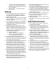
j. To reduce a fire hazard, keep machine free of grass, leaves, or other debris build-up. Clean up oil or fuel spillage and remove any fuel soaked debris. k. Allow machine to cool at least 5 minutes before storing. 11. Keep all guards, deflectors and safety devices in place and operating properly. 12. Keep your face and body back and to the side of the chipper chute while feeding material into the machine to avoid accidental kickback injuries. 13.
WARNING: - YOUR RESPONSIBILITY: Restrict the use of this power machine to persons who read, understand and follow the warnings and instructions in this manual and on the machine. NOTE: Not all safety labels shown may apply to your chipper shredder vacuum. SECTION 2: ASSEMBLING YOUR CHIPPER SHREDDER VACUUM IMPORTANT: This unit is shipped without gasoline or oil in the engine. Be certain to service engine with gasoline and oil as instructed in the separate engine manual before operating your machine.
Attaching The Nozzle • • Discharge Chute Remove three wing nuts from the front of the chipper shredder vacuum. Place nozzle in position over the three studs on unit and secure with wing nuts just removed. See Figure 2. Bag Opening Bag Wing Nuts Wing Nut Nozzle Figure 3 • Place the four straps on the top of the bag over upper handle, hooking them on the studs to secure in place. Squeeze the clamp on the drawstring and pull the drawstring tight. Release the clamp. See Figure 4.
Throttle Control Lever (Not Shown) Engine Controls The throttle control lever is located on the engine. It controls the engine’s speed and stops the engine. See separate engine manual packed with unit for details. See the separate engine manual for the location and function of the controls on the engine. Starter Handle (Not Shown) Stopping Engine The starter handle is located on the engine. Pull the starter handle to start engine. • • Move throttle control lever to STOP or OFF position.
• • • • Using the Chipper Shredder Vacuum Engines with primer: Prime engine as instructed in separate engine manual. The throttle control lever is located on the engine. Move engine throttle control lever to FAST or START position. Place one foot on the left rear wheel to prevent the unit from skidding while starting. Grasp starter handle and pull rope out slowly until engine reaches start of compression cycle (rope will pull slightly harder at this point).
SECTION 5: ADJUSTING YOUR CHIPPER SHREDDER VACUUM Drive Clutch Cable Adjustment WARNING: Do not at any time make any adjustments without first stopping engine, disconnecting spark plug wire, and grounding it against the engine. Adjust the drive clutch control if the chipper shredder vacuum moves forward with the drive clutch control disengaged, if it does not self-propel with the drive clutch control engaged, or if drive belt is slipping (unit hesitates while engine maintains the same speed).
SECTION 6: MAINTAINING YOUR CHIPPER SHREDDER VACUUM Lubrication (Refer to Figure 5) WARNING: Before performing any maintenance or repairs, stop the engine, wait until the machine comes to a complete stop, disconnect the spark plug wire and ground against the engine to prevent unintended starting. Wheels: Lubricate the rear wheels with light oil once a season. Nozzle Door Adjustment Levers: Lubricate each adjustment lever once a season with light oil.
Access Plate Hex Bolt Flat Washer Hex Nut Self-Tapping Screws Hex Lock Nuts Discharge Chute Belt Cover Self-Tapping Screws Figure 11 Hex Bolts Hex Nuts WARNING: Use caution when replacing the blades, wear heavy gloves to avoid a contact injury with the weld bolts or the housing while loosening or tightening the blades. Flail Screen • When sharpening blades, follow the original angle of grind. Also, make sure to remove an equal amount from each blade and torque hardware 250 300 in. lbs.
Safety Switch Self-Tapping Screw Hex Bolts Lower Belt Guard Hex Bolts Self-Tapping Screws Figure 14 Figure 12 • • • • • Remove the safety switch from the front of the outer housing by removing the two self-tapping screws. See Figure 12. Remove the two hex bolts and hex lock nuts which extend through the housing. Lift the flail screen out of the housing. Refer to Figure 10. Remove the outer housing and housing blades by removing the fourteen self-tapping screws.
• • Secure the impeller assembly to the crankshaft using the hex bolt, lock washer, and flat washer previously removed. Torque the bolt to 550 in. lbs. to 700 in. lbs. Place the housing blades against the inner housing. See Figure 16. Outer Housing Inner Housing Holes for Screwdrivers Figure 17 Storing Your Chipper Shredder Vacuum • • • Housing Blades Figure 16 • • • • Place the outer housing against the inner housing.
SECTION 7: TROUBLESHOOTING Problem Engine fails to start Engine runs erratic Cause Remedy 1. Spark plug wire disconnected. 2. Fuel tank empty or stale fuel. 3. Throttle control lever not in correct starting position. (If Equipped) 4. Choke not in CHOKE position. (If Equipped) 5. Blocked fuel line. 6. Faulty spark plug. 1. Connect wire to spark plug. 2. Fill tank with clean, fresh gasoline. 3. Move throttle lever to FAST position. 1. Spark plug wire loose. 2. Unit running on CHOKE. (If Equipped) 3.
Notes 15
Model 203 1 2 3 4 2 3 5 9 10 8 6 7 11 12 13 15 9 14 10 8 14 16 13 16
Model 203 Ref. No. 1. 2. 3. 4. 5. 6. 7. 8. 9. 10. 11. 12. 13. 14. 15. 16. Part No. 681-0095 712-3010 736-0242 731-1690A 764-0492 631-0069 731-1831 710-0969 720-0190 732-0754 781-0702 781-0703 738-0913 736-3084 712-0431 631-0047 777D00121 777D00183 777D01301 777I20123 777I20373 777S30041 777S30131 777S30183 Part Description Chipper Chute Hex Nut 5/16-18 Bell Washer .340 ID x .
Model 203 1 2 3 2 4 7 6 13 3 14 18 15 13 14 5 16 17 11 8 10 9 12 5 3 25 26 21 22 2 15 17 14 19 30 23 31 24 30 27 34 35 28 32 29 33 18
Model 203 Ref. No. 1. 2. 3. 4. 5. 6. 7. 8. 9. 10. 11. 12. 13. 14. 15. 16. 17. Part No. 681-0108 719-0329 715-0166 681-0107 711-0833B 736-0119 710-1054 781-0490 712-0411 736-0247 736-0217 710-1273 723-0438 710-0604A 712-0384 781-0627 712-3004A Ref. No. Part Description Impeller Ass’y Complete Flail Blade Spiral Pin Impeller Assembly Clevis Pin Lock Washer 5/16 Cap Screw 5/16-24 x 1.0 Chipper Blade Hex Lock Nut 5/16-24 Flat Washer .406 x 1/1/4 Lock Washer 3/8 Hex Cap Screw 3/8-24 x 2.
Model 203 9 11 2 5 6 4 10 6 5 1 13 17 8 3 7 4 16 15 8 17 14 12 19 18 44 49 30 24 27 27 29 25 40 45 55 35 36 48 41 34 33 32 42 23 37 54 50 52 38 51 31 47 43 50 28 26 39 46 22 53 20
Model 203 Ref. No. 1. 2. 3. 4. 5. 6. 7. 8. 9. 10. 11. 12. 13. 14. 15. 16. 17. 18. 19. 21. 22. 23. 24. 25. 26. 27. 28. Part No. 781-0677 781-0676 754-0457 748-0313 741-0413 736-0336 713-0422 710-0896 710-0603 618-0256 611-0063 10622B 634-0243 712-0456 712-3027 714-0104 736-0366 748-0188B 748-0381 748-0405 618-0255 16500A 711-1118 717-1432 721-0213 736-0187 736-0336 741-0413 Ref. No.
Model 203 5 1 6 2 4 3 7 8 3 9 20 11 10 12 8 22 2 26 21 13 15 14 13 13 12 24 16 19 26 23 12 18 29 25 26 12 28 13 30 25 26 31 27 12 18 32 34 35 30 36 13 37 38 29 34 39 29 32 35 36 13 33 37 38 40 41 38 45 20 42 43 37 44 46 47 29 38 37 44 48 46 45 47 48 22 17 18
Model 203 Ref. No. 1. 2. 3. 4. 5. 6. 7. 8. 9. 10. 11. 12. 13. 14. 15. 16. 17. 18. 19. 20. 21. 22. 23. 24. Part No. 749-1095 1539-019 711-0737 746-0714 731-1735 731-0620 731-1736 710-0841 731-1059 710-1331 710-0805 736-0451 712-3004A 725-0157 712-0138 736-0329 781-0647 710-3008 747-0815 710-0896 731-1646 719-0359 747-0929A 736-3008 Ref. No. Part Description Upper Handle Push Nut Stud Pin .250 x 1.75 Clutch Cable 56" Upper Clutch Cover Drive Lever Lower Clutch Cover Screw #10-12 x .
MANUFACTURER’S LIMITED WARRANTY FOR: The limited warranty set forth below is given by MTD LLC with respect to new merchandise purchased and used in the United States, its possessions and territories. MTD LLC warrants this product against defects for a period of two (2) years commencing on the date of original purchase and will, at its option, repair or replace, free of charge, any part found to be defective in materials or workmanship.