OPERATOR’S MANUAL ZERO TURN TRACTOR Model Numbers ZT 42 w/42" Mower Deck ZT 50 w/50" Mower Deck IMPORTANT: READ SAFETY RULES AND INSTRUCTIONS CAREFULLY Warning: This unit is equipped with an internal combustion engine and should not be used on or near any unimproved forestcovered, brush-covered or grass-covered land unless the engine’s exhaust system is equipped with a spark arrester meeting applicable local or state laws (if any).
TABLE OF CONTENTS TRACTOR PREPARATION ................................................................................................... 2 IMPORTANT SAFE OPERATION PRACTICES .................................................................... 4 SAFETY DECALS AND LABELS ........................................................................................... 7 RECORDING MODEL AND SERIAL NUMBER INFORMATION ........................................... 9 CUSTOMER SUPPORT ......................................
The tractor is shipped with an activated sealed battery, with the positive battery cable factory connected. The negative cable must be connected. POSITION DRIVE CONTROL LEVERS The drive control levers are unfastened from their respective pivot brackets and lowered for shipping purposes. The control levers must be repositioned and secured to the pivot bracket to operate the tractor.
WARNING • • • The engine exhaust, some of its constituents, and certain vehicle components contain or emit chemicals known to the State of California to cause cancer, birth defects or other reproductive harm. This unit is equipped with an internal combustion engine and should not be used on or near any unimproved forest-covered, brush-covered, or grass-covered land unless the engine’s exhaust system is equipped with a spark arrester meeting applicable local or state laws (if any).
DO: 13. Mow only in daylight or good artificial light. 14. Do not operate the machine while under the influence of alcohol or drugs. Mow across slopes, not up and down. Remove obstacles such as rocks, limbs, etc. 15. Watch for traffic when operating near or crossing roadways. Watch for holes, ruts or bumps. Uneven terrain could overturn the machine. Tall grass can hide obstacles. 16. Use extra care when loading or unloading the machine into a trailer or truck.
8. After striking a foreign object, stop the engine, remove the wire from the spark plug and thoroughly inspect the mower for any damage. Repair the damage before restarting and operating the mower. 5. Never allow children under 14 years old to operate the machine. Children 14 years and over should only operate the machine under close parental supervision and proper instruction. 6.
SAFETY DECALS AND LABELS Keep product safety graphics (decals) clean. Replace any safety graphic that is damaged, destroyed, missing, painted over or can no longer be read. Replacement safety graphics are available through your dealer. NOTI CE BATT.OIL • PTO Automatically START Disengages When START FORWARD HOURS 1/10 REVERSE REV ERSE FO R W A R D NEUTRAL PT O/ P ARK BLADE BRAKE Both Lap Bars Are Moved Into Reverse.
SAFETY DECALS AND LABELS ZT50 ZT42 KEEP HANDS AND FEET AWAY FROM ROTATING PARTS. REMOVE OBJECTS THAT CAN BE THROWN BY THE BLADE IN ANY DIRECTION. WEAR SAFETY GLASSES. DO NOT MOW WHEN CHILDREN OR OTHERS ARE AOUND. NEVER CARRY CHILDREN. USE EXTRA CAUTION ON SLOPES. DO NOT MOW SLOPES GREATER THAN 15°. MOW UP AND DOWN, NOT ACROSS. AVOID SUDDEN TURNS, USE LOW GEAR. READ OPERATOR'S MANUAL. KEEP SAFETY DEVICES WORKING.
RECORDING MODEL AND SERIAL NUMBER This Operator’s Manual is an important part of your new lawn tractor. It will help you assemble, prepare and maintain the unit for best performance. Please read and understand what it says. Before you start assembling your new equipment, please locate the model plate under the seat of the tractor and copy the information in the space provided below. A sample model plate is also given below.
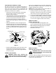
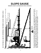
D ON 15° ED L INE, REP RES ENT IN WARNING DOT T GA 15° S LO P E Do not mow on inclines with a slope in excess of 15 degrees (a rise of approximately 2-1/2 feet every 10 feet). A riding mower could overturn and cause serious injury. If operating a walk-behind mower on such a slope, it is extremely difficult to maintain your footing and you could slip, resulting in serious injury. Operate RZT zero turn tractors across the face of slopes rather than up and down.
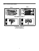
SECTION 1: CONTROLS AND FEATURES B O C A C N M D E L J F F G K H Figure 4 A. B. C. D. E. F. G. Deck Height Index Deck Lift Handle RH and LH Drive Control Levers Ignition Switch PTO Switch Transmission Bypass Rod (Not Shown) Cup Holder H. J. K. L. M. N. O.
NOTE: References to LEFT, RIGHT, FRONT, and NOTE: To prevent accidental starting and/or battery discharge, remove the key from the ignition switch when the tractor is not in use. REAR indicate that position on the tractor when facing forward while seated in the operator’s seat. A. Deck Height Index The deck height index consists of six index notches located on the front/right of the seat box frame.
• K. Fuel Tank Cap The fuel tank cap is located at the rear of the LH console. Turn the cap counterclockwise to unscrew and remove from the fuel tank. Always re-install the fuel cap tightly onto the fuel tank after removing. WARNING: Never fill the fuel tank when the engine is running. If the engine is hot from recently running, allow to cool for several minutes before refueling. Highly flammable gasoline could splash onto the engine and cause a fire.
• M. Throttle Control The throttle control is located on the LH console to the left of the operator’s seat. When set in a given position, a uniform engine speed will be maintained. ZT42 This symbol indicates the fast position. N. Choke Control - Model ZT50 ONLY The choke knob controls the position of the engine choke. Pull the knob out to choke the engine; push the knob in to open the choke. This symbol indicates the slow position. This symbol indicates the choke position. O.
SECTION 2: OPERATION GENERAL SAFETY BEFORE OPERATING YOUR TRACTOR • • Before you operate the tractor, study this manual carefully. It has been prepared to help you operate and maintain your tractor efficiently. • Familiarize yourself with the operations of all the instruments and controls. • This engine is certified to operate on unleaded gasoline. For best results, fill the fuel tank with only clean, fresh, unleaded regular or premium gasoline. DO NOt use leaded gasoline.
• The safety interlock system will shut off the engine if the operator leaves the seat with the PTO engaged, regardless of whether the parking brake is engaged. NOTE: The PTO switch must be moved to the “OFF” position to restart the engine. • The safety interlock system will shut off the PTO and the mower blades will stop if both drive control levers are moved into the reverse position. The PTO will re-engage when one or both of the levers are moved back to the neutral or forward position.
COLD WEATHER STARTING Be sure to use the proper oil for the expected temperatures (check the table in the engine manual). Follow the normal engine starting instructions above. However, allow the engine ample time to warm up before putting the tractor under load. NOTE: Always remove the key from the ignition switch to prevent accidental starting or battery discharge if the equipment is left unattended.
• Move the RH and LH drive control levers inward in the neutral position. See Figure 10. DRIVING FORWARD Faster Control Lever Moved Inward and in Neutral Slower Neutral Position Figure 11 Figure 10 • NOTE: If the control levers are not even in the neutral position, refer to Section 3 and adjust the levers so that they are even. • IMPORTANT: Always maintain your grasp on the drive control levers. Do not release the levers to slow the tractor or to return to neutral.
IMPORTANT: Always maintain your grasp on the drive control levers. Do not release the levers to slow the tractor or to return to neutral. - To turn to the right, move the right drive control lever rearward of the left lever. See Figure 13. FORWARD RIGHT TURN Turning While Driving Rearward • To turn the tractor while driving rearward, move the control levers as necessary so that one lever is forward of the other. The tractor will turn in the direction of the forward control lever.
STOPPING THE TRACTOR • Move both drive control levers to the neutral position to stop the motion of the tractor. • Push the PTO switch downward to the disengaged position. • Use the deck lift handle to raise the deck to its highest position. • If dismounting the tractor: - Move the drive control handles fully outward in the neutral position. - Engage the parking brake. - Move the throttle control lever to the fast position if operating a ZT42 tractor, or to the slow position if operating a ZT50 tractor.
IMPORTANT: When stopping the tractor for any reason while on a grass surface, always: USING THE MOWER DECK WARNING: Make certain the area to be mowed is free of debris, sticks, stones, wire or other objects that can be thrown by the rotating blades. • Place the shift lever in neutral, • Engage the parking brake, • Shut engine off and remove the key. Doing so will minimize the possibility of having your lawn ‘‘browned’’ by hot exhaust from your tractor’s running engine.
SECTION 3: ADJUSTMENTS ADJUSTING THE OPERATORS SEAT • To adjust the position of the seat, move and hold the seat adjustment lever toward the left. Slide the seat forward or rearward to the desired position; then release the adjustment lever. Make sure seat is locked into position before operating the tractor. See Figure 19. • Insert the carriage bolt through the pivot bracket and control lever slot. Slide the bell washer onto the bolt and screw on the nut knob, but do not fully tighten now.
SECTION 4: MAINTENANCE ENGINE MAINTENANCE • Engine maintenance procedures and schedules can be found in the engine manual. Follow those instructions for performing engine maintenance. If acid spills on clothing, first dilute it with clean water, then neutralize with a solution of ammonia/ water or baking soda/water. • NEVER connect (or disconnect) battery charger clips to the battery while the charger is turned on, as it can cause sparks.
CHARGING THE BATTERY SERVICING ELECTRICAL SYSTEM Test and, if necessary, recharge the battery after the tractor has been stored for a period of time. • A voltmeter or load tester should read 12.6 volts (DC) or higher across the battery terminals. A fuse is installed to protect the tractor’s electrical system from damage caused by excessive amperage. Always use the same capacity fuse for replacement. If the electrical system does not function, check for a blown fuse.
USING THE TRANSMISSION BYPASS RODS TRACTOR CREEPING If for any reason the tractor will not drive or you wish to move the tractor, the two hydrostatic transmissions are equipped with bypass rod that will allow you to manually move the tractor short distances. Creeping is the slight forward or backward movement of the tractor when the engine is running at high idle and the drive control levers are opened out in the neutral position.
TRACTOR HIGH SPEED TRACKING TRANSMISSION DRIVE BELT If the tractor tracks to one side with both drive control levers fully forward, adjust the control levers as follows: If the transmission drive belt becomes worn and causes the drive transmissions to slip, the drive belt must be replaced. To replace the drive belt, proceed as follows: • • Check for proper and balanced air pressure in both front and rear tires. Refill tires if necessary.
Emptying the fuel system: • Prior to putting the tractor in storage, monitor fuel consumption with the goal of running the fuel tank empty. TRACTOR STORAGE If your tractor is not going to be operated for an extended period of time (thirty days to approximately six months), the tractor should be prepared for storage. Store the tractor in a dry and protected location. If stored outside, cover the tractor (including the tires) to protect it from the elements.
SECTION 5: MOWER DECK Rolling the belt off the PTO pulley. This section contains removal, installation, adjustment, and maintenance information for the 42-inch (ZT42) and 50-inch (ZT50) mower decks. • DECK REMOVAL Remove the mower deck from the tractor as follows: 1. Move the tractor to a level surface, disengage the PTO, stop the engine, and set the parking brake. 2. Move the deck gauge wheels to their highest setting (lowest deck setting). 3.
• • Slide the deck forward so that the deck front hanger rod can be lifted out of the two slots of the front deck bracket. After lifting the front hanger rod out of the slots, slide the deck rearward so that the rod can no longer engage the slots. Using care to prevent the front hanger rod from falling back into the deck slots, gently slide the cutting deck (from the right side) out from underneath the tractor. • Route the backside of the belt around the fixed idler pulley of the deck.
- Retighten the hex cap screw on the right deck hanger bracket when proper adjustment is achieved. LEVELING THE MOWER DECK When leveled correctly the mower deck should be level side to side, and should be approximately a 1/8 to 1/4 inch lower in the front of the deck. • Side to Side Leveling If the cutting deck appears to be mowing unevenly, a side to side adjustment can be performed.
• From the front of the tractor, loosen the outer nuts on the deck front hanger rod, and turn them away from the inner nuts. See Figure 32. • With the deck set at the desired height, check the distance between the gauge wheels and the ground. If the gauge wheels are near or touching the ground, they should be raised. If the gauge wheels are too high, they should be lowered. • Remove the lock nut securing one of the gauge wheel shoulder screws to the deck. Remove the gauge wheel and shoulder screw.
• The cutting blades must be kept sharp at all times. Sharpen the cutting edges of the blades evenly so that the blades remain balanced and the same angle of sharpness is maintained. Pull back the lock collar of the nozzle adapter and push the adapter onto the deck wash nozzle at the left end of the 42" mower deck, or onto one of the deck wash nozzles at either end of the 50" mower deck. Release the lock collar to lock the adapter on the nozzle. See Figure 34.
DECK LUBRICATION REPLACING THE DECK DRIVE BELT • • Remove the deck from beneath the tractor, (refer to Deck Removal on page 28). • Remove the hex tapping screws securing the belt covers to the deck and remove the belt from the spindle pulleys. Refer to Figure 36. • Depending on which deck (42" or 50") you are working on, install the new belt around the spindle pulleys as shown in the applicable graphic of Figure 36. Reinstall the belt covers.