
Installation Sheet
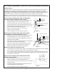
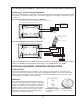
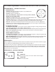

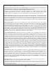
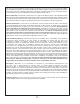
Table Of Contents

7
OPTIONAL EQUIPMENT INSTALLATION GUIDELINES (continued)
VIRTUAL SPOUT
Incoming water is connected to mixing valves mounted on the tub, surrounding deck or wall. Output from
the mixing valves must then be tied into either a Wilkins Dual-Check Valve or Atmospheric Vent Valve,
depending on local backow prevention plumbing codes. If code requires an Atmospheric Vent Valve, you
can use either a tub mounted or deck mounted Breda Valve or an In-wall Acme Valve. Output from any of
these valves is then connected to the Virtual Spout. See specic installation instructions below.
NOTE: An In-wall Acme Atmospheric Vent Valve and Wilkins Dual-Check Valve is packaged with the Virtual Spout and is
included in the price. If using a deck mounted Breda instead of an In-wall Valve, the Breda Valve must be purchased separately.
INSTALLATION INSTRUCTIONS FOR TUB-MOUNTED
OR DECK-MOUNTED BREDA VALVE (FIGURE 1)
• Before you begin, check and observe local plumbing codes.
• Install mixing valves on tub, surrounding deck or wall.
• Connect the mixed water line from the mixing valves to the
bottom center inlet port on the Breda Atmospheric Vent Valve.
• The Breda Valve is pre-plumbed to direct the water flow to the
filler port located on the inside wall of the tub.
• MTI recommends providing access to the Breda
Valve for any future servicing.
• Check all plumbing for leaks and proper operation.
INSTALLATION INSTRUCTIONS FOR ACME IN-WALL
ATMOSPHERIC VACUUM BREAKER
(FIGURE 2)
• Before you begin, check and observe local plumbing codes.
• Install mixing valves on tub, surrounding deck or wall.
• Connect mixed water line from the mixing valves to the In-Wall
Atmospheric Vacuum Breaker.
• Make sure that the bottom of the Atmospheric Vacuum Breaker
is a minimum of 6" above the top of the tub.
• Connect the output from the In-Wall Atmospheric Vacuum
Breaker to the copper pipe leading to the Virtual Spout.
• Check all plumbing for leaks and proper operation.
IMPORTANT NOTES FOR ACME IN-WALL UNIT
• The Atmospheric Vacuum Breaker is subject to normal maintenance and therefore must be installed
in such a way that it will be accessible after the tub installation is complete.
• Since, under backsiphonage conditions, small amounts of water may be spilled through the air port,
the Atmospheric Vacuum Breaker must be located and installed in such as way that the water will
be captured and contained.
INSTALLATION INSTRUCTIONS FOR WILKINS DUAL-
CHECK VALVE
(FIGURE 3)
• Before you begin, check and observe local plumbing codes.
• Install mixing valves on tub, surrounding deck or wall.
• Connect mixed water line from the mixing valves to the Wilkins
Dual Check Valve.
• Connect the output from the Wilkins Dual Check Valve to the
copper pipe leading to the Virtual Spout.
• Check all plumbing for leads and proper operation.
Virtual Spout
Breda Valve Vent
Mixed Water Line
Hot and Cold
mixing valves
mounted on tub,
surrounding
deck or wall
(not supplied)
Wilkins Dual Check Valve
Figure 1
Top Rim
of Tub
Hot and Cold
mixing valves
mounted on tub,
surrounding
deck or wall
(not supplied)
Virtual Spout
Acme In-Wall Vent
6
" minimum
Interior View of Wall
Wilkins Dual Check Valve
Figure 2
Wilkins -
mixing valves
Figure 3