
Installation Sheet


8
ADDITIONAL INSTRUCTIONS FOR TUBS EQUIPPED WITH AN AIR BATH
The instructions on pages 8-10 apply to ALL air baths.
If your bath came equipped with an air system, there are several considerations and
important installation procedures to follow.
1.
The
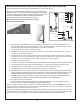
blower and check valve must be remotely located from the tub (See Illustration A on next page).
The blower and check valve may be remote mounted up to 8' from the bath. The check valve must be
located at least 2" above the top rim of tub. The air hose leading to the blower may be installed under
the floor and the blower and check valve located inside a utility or linen closet. MTI does not recom-
mend locating the blower more than 8' from the tub to prevent heat loss from the blower to the tub. Use
care not to crush or restrict the airflow in the line in any way. NOTE: 1" schedule 40 PVC pipe and
pipe insulation may be used to help retain the warmth from the blower. Do NOT use insulation
within 8" of the blower. The blower needs sufficient air space surrounding it for circulation
(minimum of 2 cubic feet), and must be installed in a climate controlled environment.
2. A 110V, 15 Amp GFCI outlet is required for the air blower. The
blower is equipped with a 29" power cord to plug directly into
this outlet. Keep in mind, the outlet, as well as any electrical
equipment, must be easily accessible for any future service.
The blower draws 9.5 amps.
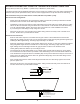
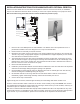
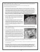
3. The air hose that attaches to the check valve and manifold
(factory installed underneath the tub), can exit the tub
either through the side of the pedestal base or from directly
underneath the tub, depending on the blower location. Side
exit would only be used in cases where the tub is very close
to the wall, or has cabinetry around it to conceal the plumbing.
MTI does not pre-drill the pedestal base for side exit
(see photo A).
4. The check valve MUST be mounted at least 2" above the top rim of the tub. A common location is near the
blower in a closet or cabinet. The check valve can be mounted to the framing or wall with pipe hanger, pipe
clamp, metal straps or wire ties
(See Illustration A on next page).
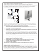
5. Use 1" PVC flexible hose or rigid schedule 40 to connect the
check valve to the tub. Connect the check valve to the blower
using the grey hose provided. Secure blower using wood
screws through the mounting feet. Connect the sensor wires to
the blower (See Illustration A on next page). The sensor wires
are factory installed to the two small chrome sensor heads
on either side of the drain (see photo B) and allow the purge
cycle to activate (see page 10 and/or step 8 at bottom of this
page for more details about the autormatic purge cycle). Do not
attempt to remove the sensor wires from the tub. The sensor
wires must be located and attached to the blower for proper
operation.
6. Connect the keypad cable to the remote control module and the module to the blower. The keypad
plugs into the jack on the right side and the cable from the left jack connects to the blower
(See Illustration B on next page).
7. The keypad can be mounted convenient to the bather, or simply left unattached if only the remote
control is desired.
8. Plug the blower into the outlet and test for operation. After the tub is turned off, the light on the keypad
will be flashing, indicating the purge cycle is activated. Note: All air baths are equipped with an
automatic drying cycle. The blower will turn on for 1-2 minutes approximately 7 minutes after
the bath is drained. The blower LED blinks during the drying cycle countdown. This drying cycle
cannot be cancelled. Any attempt to cancel this cycle only resets the countdown timer.
Manifold
Air Hose
Sensor
Wire
Sensor
Wire
Photo A
Photo B
Connects
to blower