
User's Manual


BDA Installation and Operating Guide
Version 1.0 iii
List of Figures
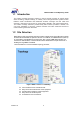
Figure 1 BDA Solution for in-building ................................................................................................6
Figure 2 Ceiling mount of patch antenna ..........................................................................................7
Figure 3 Ceiling mount of omni antenna ........................................................................................8
Figure 4 Wall mount of patch antenna ...............................................................................................8
Figure 5 Pole mount of Yagi antenna .................................................................................................8
Figure 6 BDA with AC power cord.......................................................................................................9
Figure 7 Interfacing with Link antenna and Service antenna.....................................................12
Figure 8 Interfacing port of top side.................................................................................................12
Figure 9 Cable Connection of BDA ...................................................................................................13
Figure 10 Connection of Laptop PC .................................................................................................13
Figure 11 Cable Connection of the BDA..........................................................................................14
Figure 12 Interfacing port of BDA bottom side..............................................................................14
Figure 13 Connection of Laptop PC in BDA ...................................................................................15
Figure 14 Assembling of the BDA .....................................................................................................16
Figure 15 Assembly of electrical power cable of the BDA..........................................................17
Figure 16 Electrical power cable connection of the BDA ...........................................................17
Figure 18 Install bracket of the BDA on the wall ...........................................................................18
Figure 19 Cable arrangement at the BDA........................................................................................19
Figure 20 Total network configuration for indoor .........................................................................20
Figure 21 Required Items for Installation........................................................................................22
Figure 22 Installation of Operating Software (GUI).......................................................................22
Figure 23 Installation starting of Operating Software ..................................................................23
Figure 24 Selection Folder of Operating Software Installation..................................................23
Figure 25 Creation of a shortcut in a start menu folder ..............................................................24
Figure 26 Setup review window.........................................................................................................24
Figure 27 Progress view of installation ...........................................................................................25
Figure 28 Installed completed ............................................................................................................25
Figure 29 Display launcher Window .................................................................................................26
Figure 30 Initial window.......................................................................................................................26
Figure 31 Starting of Operating Software........................................................................................27
Figure 32 COM port set-up..................................................................................................................27
Figure 33 Debug Window ....................................................................................................................30
Figure 34 Alarm Log Window .............................................................................................................31
Figure 35 Power Log Window
............................................................................................................32
Figure 36 Alarm Mask Window...........................................................................................................32