Pulse Width Modulated 4-Quadrant Servo Controller Series TBF-R Installation Manual For electronic commutated servo motors 2101 North Broadway New Ulm, MN 56073 0199 Telephone: 507-354-1616 ©MTS Automation 1999 Fax: 507-354-1611
Important! Reading these instructions prior to start-up is absolutely necessary. Dear customer, The following items and the “Safety Instructions” are for your benefit and are designed to protect the amplifier from damage caused by incorrect use. According to the product liability law, everyone who puts a product which constitutes a risk for life and limb into circulation is obligated to provide safety instructions. These instructions should be clearly defined and should have an informative nature.
Table of Contents Page 1 Safety Instructions.....................................................................................................................1 1.1 General notes ............................................................................................................................ 1 1.2 Qualified personnel.................................................................................................................... 1 1.3 Designated use............................................
List of Figures Figure 1: Principle of the amplifier, D0140A.dsf....................................................................... 6 Figure 2: Block diagram, D0158A.dsf........................................................................................ 7 Figure 3: Jumper setting, PC-TBF/2.plt .................................................................................... 11 Figure 4: Front views, FRONTS_TBFR.dsf..............................................................................
1 Safety Instructions 1.1 General Notes This start-up manual describes functions and gives all necessary information for the designated use of the subassemblies produced by Custom Servo Motors. The manufacturer is responsible for the preparation of an instruction manual in the national language of the end user. The preparation of machine-specific risk analyses is also the manufacturer's duty.
1.5 Safety Notes As the subassemblies are intended for installation in machines, freely accessible parts may carry dangerous voltage. The manufacturer must ensure adequate protection against contact. Only qualified personnel, who knows the contents of these start-up instructions, must execute any work on these subassemblies. The instructions contained in this manual have to be observed strictly, as a wrong handling causes additional risks. ! 1.
1.7 Maintenance / Service For measuring or test work on any live device, please observe the relevant accident prevention regulations. The work must be done only with suitable measuring instruments and tools. Service work on subassemblies is done exclusively by Custom Servo Motors staff. Incorrect repair work by unqualified persons may lead to damage to material property, and bears a risk of injuries or mortal injuries.
2 Technical description 2.1 General Information The series R amplifiers (= resolver) are servo amplifiers for speed control of brushless servo motors. They extract the information for the sine commutation of the motor and for the speed feedback from the signals of the resolver, attached to the motor. In addition to that, incremental encoder signals are simulated by these signals. This allows the realization of favorable solutions for a large range of applications with low and medium power levels.
2.2 Technical Data Series Nominal voltage Nominal current (peak value) Pulse current (peak value) Intermediate circuit voltage max. min. TBF60/5R TBF60/10R TBF120/7R 60V 5A 15A 85VDC 25VDC 54 AC – 60V 10A 25A 85VDC 25VDC 54VAC – internal 93% 1.5V 9.5kHz 19kHz 1kHz 0.8mH 120V 7A 18A 170VDC 70VDC 95VAC internal 0.5kg 0.8kg 1.
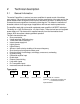
2.3 Principle of the Amplifier The three-phase servo amplifiers of Series TBF are based on the principle of the speed control with secondary current control loop. In addition to that the current-mode logic controls the commutation of the electronically commutated servo amplifier (brushless). The signal flow of this functional group is shown in the following figure.
2.
2.5 Function Description The function of the amplifier is described by means of the block diagram shown in Figure 2. 2.5.1 • Power Supply Power amplifier: Rectification and filtering form the direct voltage (intermediate circuit voltage UB), necessary to operate the power amplifier, from the AC power supply. This intermediate circuit voltage can also be fed directly as d.c. voltage.
• Current-mode control and current controller As shown in the block diagram, the current-mode control must be passed through first, to form the actual current set value for the current controller of the U-conductor current and of the V-conductor current. The nominal current of the speed controller output (conductor current) is converted, depending on signals of the resolver, in two current set values with an offset of 120º and fed to the current controllers for the phases U and V.
! For safety reasons enable is possible only when the device is ready for operation! This avoids that the motor starts running in an uncontrolled manner when applying the operating voltage while the enable signal is already applied. That means a permanent wired connection of e.g. +24V after the enable input ensures that the motor will not start running when switching on the operating voltage.
2.6 Function as Current Controller In the case the device was not ordered as current controller, the adjustment ex factory is "Speed control". In some applications it may be useful to operate the TBF amplifier as a pure current controller, because a torque control is desired or the speed controller in the master control is already realized. To set the amplifier to current control or speed control set the three soldering jumpers JP9, JP10 and JP11 (see figure) as follows: JP9.1 to JP9.
2.7 List of Possible Adjustments and Indicators 2.7.1 The LEDs LED1 (green) Indicates readiness of the device; lights also when the amplifier is not enabled. LED2 (yellow) l2t- current limiting is active LED3 (red) Fault (overcurrent, overvoltage, overtemperature). LED4 (yellow) Ballast circuit operates (only for 120V devices). 2.7.
2.7.4 The Soldering Jumpers JP1 to JP8 JP9 JP10 JP11 JP12 JP13 2.7.5 P6 P7 P8 P9 P10 2.7.6 S1 Adjustment only for devices without resolver. Closed when operating the device as speed controller, open for current control.
2.
3 Connection of the device 3.1 Pin Assignment Conn. 1 (F48) 2z 2b 2d Integral off Pos. Stop Neg. Stop 26z 26b 26d Power GND Power GND Power GND 4z 4b 4d GND Ref. Nominal speed input (-) Nominal speed input (+) 28z 28b 28d Motor W Motor W Motor W 6z 6b 6d + 5V Ready Ready 30z 30b 30d Motor V Motor V Motor V 8z 8b 8d + 15V Enable input Tachometer output 32z 32b 32d Motor U Motor U Motor U 10z 10b 10d N.C. Track Ι+ Track Ι- 12z 12b 12d N.C.
3.2 Explanation of the pin assignment 3.2.1 Connector 1 (F48) 2z Integral switch-off The integral-action component of the speed controller can be switched off at this input by injecting a high signal (15 to 30V). This may be useful, e.g. for positioning tasks. The motor does not drift slowly, but has a lower holding moment. During the normal operation, this input is inactive. The input is not to be wired for this case or is to be connected to ground.
8z +15V Output of the +15V electronic voltage for supply of the limit switch inputs Pos.Stop, Neg.Stop. Carrying capacity together with 18d: 10mA. 8b Enable input This connection is to be applied for enable input to a voltage of +15V to +30V, after the ready contact is closed. The motor is disabled with the input open. ! As in chapter 2.5 the following applies: Enable of the motor is possible only when the device is ready for operation (green LED lights).
Normally no external current limiting is used. In this case the input can be switched to +15V. 18z GND 0V reference potential for +5V, +15V, and -15V. 18b -15 V 15V supply for external use. Carrying capacity -10mA. 18d +15 V -15V supply for external use. Carrying capacity together with 8z= 10mA. 20z,b,d +UB Plus pole of the d.c. intermediate circuit. Here the plus pole of a probably existing external d.c. voltage can be supplied by circumventing the internal rectifier.
each have to be connected parallel.
3.2.2 Connector 2 (D-SUB/9-pins/socket) Connector 2 is intended for connecting a resolver. A two-pole transmitter with a transformation ratio of 0.5 is required as resolver. The input voltage of the rotor should be suitable for 7Vrms with 10kHz. 1 S4-Resolver Input for the stator signal S4 of a two-pole resolver. 2 S2-Resolver Input for the stator signal S2 of a two-pole resolver. 3 S3-Resolver Input for the stator signal S3 of a two-pole resolver.
3.3 Wiring A careful wiring is absolutely necessary to guarantee a troublefree operation of the servo amplifier! The control line for the servo amplifier, the signal lines of the motor and the motor lines are to be wired separately. See also ÑMeasures for an installation in conformity to the EMC directive. 3.3.1 Protective Earth Terminal Power GND (ST1 26z,b,d) must be connected with the protective earth terminal. Control unit and amplifier must have an equal potential.
3.3.4 Control Lines And Signal Lines Between Master Control Unit And Amplifier For the definition of the speed reference, the master control unit normally provides an output of a digital/analogue converter. This output signal normally is measured against ground or against reference voltage. The input at the amplifier is a differential input with set value+ at 4d and set value- at 4b. The lines at these inputs have to be run to the control unit in the same cable.
3.4 Connection Diagrams 3.4.
3.4.
3.5 Measures for an Installation in Compliance with the EMC Directives Because of the compact design of servo amplifiers, no complete noise suppression measures are possible without modifying the design. Therefore the proposed measures shall help to keep the EMC directive for the total system. These measures are necessary only for the used inputs and outputs. In addition to that a single total interference suppression of the mains lead of all electronic subassemblies, installed in the system, is possible.
Figure 7: Installation in Compliance with the EMC Directives 26
4 Set-up 4.1 Connection When the servo amplifier is used together with one of our motors, the connection does not cause any problems. In 3.4 you will find the connection diagrams. Connect the motor power contacts U, V, W, earth and shield as described there. The resolvers are also connected as described in 3.4. When using an auxiliary drive together with the servo amplifier TBF, we offer to work out the correct connection diagram for you. 4.
4.3 Switching On and Configuration 4.3.1 Procedure Until Amplifier is Enabled Set enable input to logical 0! Give a speed reference of 0V! Switch on control unit and amplifier supply! Release the brake of the motor, if available! Set enable input to logical 1! Turn P3 to the left, if the motor vibrates, until the vibration stops 4.3.2 Configuration of the Speed Controller Amplification For the configuration of the amplification, the motor has to be coupled to load.
4.3.3.2 Continuous Current Leave P2 in the position determined as described above, adjust P5 with five turns from left stop. Once again, move the motor with minimum speed to a mechanical stop and leave the set value at the amplifier so that the motor still tries to move towards the stop. Neither limit switch, nor IAB must be active. After expire of the pulse current phase, the current is automatically reduced to the continuous current, adjustable at P5. For adjusting P5, always turn slowly.
5 Optimizing the Controller Response 5.1 Amplification setting of the current regulators The adjustment a.c. amplification of the current regulators is done with the resistors R25 (standard 4.7kOhm) and R26 (standard 4.7kOhm) (see Figure 16), where each resistor is part of a voltage divider. Smaller resistor values increase the amplification. A response is seldom necessary here.
5.4 Integral-Action Component of the Speed Controller The capacitor C27 is responsible for the integral-action component of the speed controller (see Figure 17). The standard value of C27 is 220nF. 5.5 Direct Voltage Amplification of the Speed Controller The resistor R71 is intended for modifying the static rigidity (see Figure 17). The rigidity decreases with increasing resistor value. The standard value is 330Ohm. 5.
6 Troubleshooting Green LED (POWER.) does not light, axis does not move, no holding torque: • -15V or +15V or +5V overloaded by external consumers or short-circuited. • Fuse S1 is defective. • External fuse to the power amplifier is defective. Green LED (POWER.) lights, axis does not move, no holding torque: • Interruption of the motor lines. • Power amplifier enable is missing. • Power amplifier enable took place but the device was not ready. • Input Iextern is not wired. • Input Pos.
Red LED (FAULT) lights: • Operational voltage too high (8V ±0.4 at MP4). • Braking energy too high (8V ±0.4 at MP4). • The thermal switch reacted, as the heat sink temperature is >80º (7V ±0.4 at MP4). • Short-circuit in the motor or ground contact of a motor line (9V ±0.4 at MP4). Uncontrolled high motor speed: • Wrong polarity of the resolver or wrongly adjusted. • Wrong polarity of the motor. Motor does not reach the desired speed: • Speed reference values attenuated too strong by P1.
7 Options 7.1 Ballast circuit A ballast circuit is necessary when the regenerative energy from motor and load is larger than the energy, which can be taken up by the filter electrolytic capacitors, until the maximum voltage is reached. Because of the relatively large capacitor in the power supply unit: the TBF60/5R normally can do without a ballast circuit.
7.2 Bus boards 7.2.1 For 19" sub-racks (article no. TBF/BUS-S) Pin assignment of the screw-type terminals: 1 2 3 4 5 6 7 8 9 10 11 12 13 Int. Off Neg. Stop Pos. Stop +5V Ready 13 Ready 14 Track ITrack ATrack BNC NC NC Iext.
T B F /B U S M KK 1A 1 S T1 2Z 32 D 42 Figure 8: Pin Assignment – 19” sub-rack 36 21 B Z
7.2.
7.2.
7.2.4 Pin assignment for wall mounting (article no.: TBF/BUS-W) Pin assignment of the screw-type terminals: 1 Set value8 Set value+ 2 Enable 9 Ready 14 3 Iext 10 Pos Stop 11 GND 4 +15V 12 GND 5 Int.off 13 Track B+ 6 Track A+ 14 Track B7 Track A- 15 16 17 18 19 20 21 Tachometer output Ready 13 Neg.
28 40 Power GND 35 GND 42 NC
7.2.5 For Wall Mounting with Higher Demands to EMC (Article No.: TBF/BUS-WE) Pin assignment of the screw-type terminals: The bus board TBF/BUS-WE has the same pin assignment for the screw-type terminals as the bus board TBF/BUS-W (see Figure 11).
8 APPENDIX 8.1 Dimensional drawing TBF60/5R 3 . 9 4 in . ST 1 P C - T B F /2 1 . 5 9 in . Figure 13: Dimensional Drawing TBF60/5 42 5 .0 5 in.
TBF 60/10R 3 .9 4 in . ST1 P C - T B F /2 1 .5 7 i n . 2. 19 in . 5 .0 5 i n .
TBF 120/7R 3 .9 4 i n . ST1 P C - T B F/2 3 .1 8 i n . Figure 15: Dimensional Drawing TBF120/7 44 5 . 05 in .
8.1.
8.1.
8.1.