
Software Owner's manual


CAN Bus Interface
Note:
CAN Bus interface support is not available for MTS FlexTest SE Controllers.
CAN Bus Interface Requirements
A controller area network (CAN) bus interface requires a CAN bus controller mezzanine card that
is installed on a processor board.
The CAN bus card can include multiple CAN controllers that are configured and assigned
independently. The mezzanine card provides a network connector for each CAN bus port.
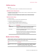
CAN Bus Interface Setup
1. Open the .hwi file.
2. Click the Controller icon, and then click the Miscellaneous tab.
3. From the # of CAN Bus Interfaces list, select 1.
A series of CAN bus icons appear under the processor icon.
4. Configure the CAN bus interface as shown in the following table.
DescriptionItem
Type: Select the model number of the CAN bus controller
mezzanine card that is installed on the processor board.
CAN Bus Icon
Each port icon represents a separate CAN bus controller port that
you can configure independently.
Port Icon(s)
Baud Rate: Enter baud rate for the CAN bus port’s RS-485 interface.
Frame Format: select the frame (message) format required by the
CAN. Selections include Basic or Extended.
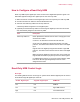
Modbus Interface Settings
A Modbus Interface consists of a networked Modbus node that connects to the controller processor
through an Ethernet network switch. A Modbus node includes a Modbus chassis (DIN rail) populated
with various modules including an Ethernet TCP/IP Fieldbus Coupler.
DescriptionItem
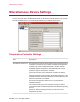
# of Modbus Interfaces: Enter the number of Modbus interfaces.
Each Modbus interface (Modbus node) consists of a DIN rail,
modules, and an Ethernet TCP/IP Fieldbus Coupler.
Miscellaneous Tab (Controller
icon)
MTS Series 793 Utility Software 83
HWI Hardware Settings