Operating Instructions Diesel engine 12 V 2000 S96 16 V 2000 S96 MS150095/01E
Printed in Germany © 2012 Copyright MTU Friedrichshafen GmbH This Publication is protected by copyright and may not be used in any way whether in whole or in part without the prior written permission of MTU Friedrichshafen GmbH. This restriction also applies to copyright, distribution, translation, micro‐ filming and storage or processing on electronic systems including data bases and online services.
Table of Contents 1 Safety 1.1 1.2 1.3 1.4 General conditions Personnel and organizational requirements Transport Safety regulations for maintenance and repair work 1.5 Auxiliary materials, fluids and lubricants, fire prevention and environmental protection 1.6 Conventions for safety instructions in the text 5 Troubleshooting 5 6 7 8 11 13 Engine – Overview Engine side and cylinder designations Engine – Main dimensions Firing order Technical Data 2.5.
6.11.2 Centrifugal oil filter – Cleaning and filter sleeve replacement 6.12 Coolant Circuit, General, HighTemperature Circuit 6.12.1 6.12.2 6.12.3 6.12.4 6.12.5 6.12.6 6.12.7 Drain and vent points Engine coolant – Level check Engine coolant – Change Engine coolant – Draining Engine coolant – Filling Engine coolant pump – Relief bore check Engine coolant – Sample extraction and analysis 6.12.8 Coolant filter – Replacement 6.13 Low-Temperature Circuit 6.13.1 6.13.2 6.13.3 6.13.4 6.13.5 6.13.
1 Safety 1.1 General conditions General In addition to the instructions in this publication, the applicable country-specific legislation and other com‐ pulsory regulations regarding accident prevention and environmental protection must be observed. This state-of-the-art engine has been designed to meet all applicable laws and regulations.
1.2 Personnel and organizational requirements Personnel requirements All work on the engine shall be carried out by trained and qualified personnel only. The specified legal minimum age must be observed. The operator must specify the responsibilities of the operating, maintenance and repair personnel. Organizational measures This publication must be issued to all personnel involved in operation, maintenance, repair or transporta‐ tion.
1.3 Transport Transport Also valid for 12V engines Only use the lifting eyes provided to lift the engine. Only use transport and lifting devices approved by MTU. Take the engine's center of gravity into account. The engine must only be transported in installation position, max. permissible diagonal pull 10°.
1.4 Safety regulations for maintenance and repair work Safety regulations for maintenance and repair work Have maintenance and repair work carried out by qualified and authorized personnel only. Allow the engine to cool down before starting maintenance work (risk of explosion of oil vapors). Before starting work, relieve pressure in systems and compressed-air lines which are to be opened. Take special care when removing ventilation or plug screws from the engine.
Welding work Never carry out welding work on the assembly, system, or engine-mounted units. Cover the engine when welding in its vicinity. Do not use the assembly or system as ground terminal. Do not route the welding lead over or near the wiring harnesses of MTU systems. The welding current may otherwise induce an interference voltage in the wiring harnesses which could conceivably damage the electrical system. Remove parts (e.g. exhaust pipes) which are to be welded from the engine beforehand.
TIM-ID: 0000000879 - 023 For conducting light-beam procedures and measurement work, only the following laser devices must be used: • Laser devices of classes 1, 2 or 3A. • Laser devices of class 3B, which have maximum output in the visible wavelength range (400 to 700 nm), a maximum output of 5 mW, and in which the beam axis and surface are designed to prevent any risk to the eyes.
1.5 Auxiliary materials, fluids and lubricants, fire prevention and environmental protection Fire prevention Rectify any fuel or oil leaks immediately; even splashes of oil or fuel on hot components can cause fires – therefore always keep the engine in a clean condition. Do not leave cloths soaked with fluids and lubri‐ cants lying on or near the assembly or unit. Do not store inflammable material near the assembly or unit.
Lead • When working with lead or lead-containing compounds, avoid direct contact to the skin and do not inhale lead vapors. • Adopt suitable measures to avoid the formation of lead dust. • Switch on extraction system. • Wash hands after contact with lead or lead-containing substances. Compressed air Observe special safety precautions when working with compressed air: • Pay special attention to the pressure level in the compressed air network and pressure vessel.
1.6 Conventions for safety instructions in the text DANGER WARNING CAUTION NOTICE Note: In the event of immediate danger. Consequences: Death or serious injury • Remedial action In the event of potentially dangerous situations. Consequences: Death or serious injury • Remedial action In the event of dangerous situations. Consequences: Minor injury or material damage • Remedial action In the event of a situation involving potentially adverse effects on the product. Consequences: Material damage.
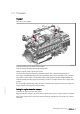
2 Product Summary 2.1 Engine – Overview 12/16 V 2000 C66/S96 This overview also applies to 16 V 2000 C66 and 16 V 2000 S96 engines. Exhaust turbocharger Air intake/air supply EGR cooler Intercooler Monitoring, control and regulation equipment, general electr.
Key to the engine model designation C/S Application: C, charge-air cooling in internal circuit, with piston cooling Application S: Exhaust turbocharging with supercharger Application segment (0, 1, 2,...,9) 6 Design index (0, 1, 2,...
2.2 Engine side and cylinder designations Engine sides are always designated as viewed from the driving end (KS). The cylinders of the left engine side are designated "A" and those of the right side "B" (as per DIN ISO 1204). The cylinders of each bank are numbered consecutively, starting with No. 1 at the driving end. Other components are numbered in the same way, i.e. starting with No. 1 on driving end.
2.3 Engine – Main dimensions Engine model / Dimension Engine model / Dimension 12 V 2000 C66/S96 16 V 2000 C66/S96 Length (A) approx. 2028 mm approx. 2378 mm Width (B) approx. 1276.5 mm approx. 1287 mm Height (C) approx. 1429 mm approx.
2.
2.5 Technical Data 2.5.1 12/16V 2000 S96 engine data Explanation: DL BL A G R L N X Ref. value: Continuous power Ref. value: Fuel stop power Design value Guaranteed value Guideline value Limit value, up to which the engine can be operated, without change (e.g.
Number of cylinders 12 16 Cylinder displacement Liters 2.233 2.233 Total displacement Liters 26.80 35.73 16.5 16.
GENERAL OPERATING DATA Number of cylinders 12 16 0 0 Cold start capability: air temperature (w/o start aid, w/o preheat‐ R ing) - (case A) °C Firing speed, from R rpm 100 100 Firing speed, to R rpm 120 120 12 16 INCLINATIONS, STANDARD OIL SYSTEM (reference: waterline) Number of cylinders Longitudinal inclination, continuous max. driving end down (Op‐ L tion: max. operating inclinations) Degrees (°) 10 10 Longitudinal inclination, continuous max. driving end up (Option: L max.
3 Operation 3.1 Putting the engine into operation after extended out-ofservice periods (>3 months) Preconditions ☑ Engine is stopped and starting disabled. ☑ MTU Fluids and Lubricants Specifications (A001061/..) are available. Putting into operation after long out-of-service periods (>3 months) Action Engine Depreserve (→ MTU Fluids and Lubricants Specifications A001061/..). Lube oil system Check engine oil level (→ Page 69).
3.2 Putting the engine into operation after scheduled out-ofservice-period Preconditions ☑ Engine is stopped and starting disabled. Putting into operation Action Lube oil system Check engine oil level (→ Page 69). Coolant circuit Check engine coolant level (→ Page 79), check charge-air coolant level (→ Page 88). Coolant circuit Preheat engine coolant with coolant preheating unit, if fitted. Fuel prefilter (if fitted) Drain water and contaminants, see manufacturer's documentation.
3.3 Tasks after extended out-of-service periods (>3 weeks) Tasks after extended out-of-service periods (>3 weeks) Operate fuel treatment system for at least 5 minutes. Start up fuel treatment system (→ Page 26). Shut down fuel treatment system (→ Page 34). TIM-ID: 0000007730 - 005 Note: 1. 2.
3.4 Checks prior to start-up Checks prior to start-up 1. 2. 3. 4. 5. 6. Result: TIM-ID: 0000007736 - 005 7. Result: Check tank and the entire pipework for cleanness. If microorganisms are detected: a) Clean affected components. b) Disinfect affected components with biocides (→ MTU Fluids and Lubricants Specifications A001061/..). Close drain valves on housing. Open all supply and discharge valves. Switch on fuel treatment system (→ Page 29). Check direction of rotation of pump.
3.5 Fuel treatment system – Putting into operation Fuel treatment system – Overview 1. 2. Result: Switch on fuel treatment system (→ Page 29). Check the differential pressure at differential pressure gauge (8). Differential pressure in a new system: 0.1 bar to 0.3 bar. If no differential pressure is measured, the coalescer filter element is probably being bypassed. 1. Remove coalescer filter element (→ Page 103). 2. Check sealing faces on coalescer filter element and in the pressure tank.
Simulation of filter replacement with the engine running: HAT 1. 2. 3. 4. Result: 5. Result: 6. Note: 7. Result: Switch on fuel treatment system (→ Page 29). Start engine (→ Page 28). Run engine at idling speed. Close ball cock (5) at the inlet to the fuel treatment system. The pressure upstream of the fuel treatment system increases until the overflow valve at the pump unit opens and fuel flows through bypass (3) and bypass (2). Open ball cock (19). Fuel emerges.
3.6 Starting the engine Preconditions ☑ Engine is not connected to load. DANGER WARNING Unguarded rotating and moving engine components. Risk of serious injury – danger to life! • Before barring or starting the engine, make sure that nobody is in the danger zone. Engine noise above 85 dB (A). Risk of damage to hearing! • Wear ear protectors. TIM-ID: 0000010107 - 004 Start engine (For required operations, refer to the documentation of the vehicle/plant manufacturer).
3.7 Fuel treatment system – Switching on Preconditions ☑ The on-board power supply is switched on. CAUTION Damage to engine/plant. Major material damage! • Before switching on, ensure that the engine/plant is ready for operation. • Before switching on, ensure that all housings are closed. • Before switching on, ensure that no work is in progress anywhere on the entire system. Switching on fuel treatment system Carry out checks prior to start-up (→ Page 25). Switch on master switch on switch cabinet.
3.8 Operational checks DANGER WARNING Unguarded rotating and moving engine components. Risk of serious injury – danger to life! • Take special care when working on a running engine. Engine noise above 85 dB (A). Risk of damage to hearing! • Wear ear protectors. Operational checks Item Action Control and display panels Check readings of operational data (speed, temperature, pressures). Engine oil Check engine oil level (→ Page 69).
3.9 Stopping the engine Preconditions ☑ Engine is not connected to load. CAUTION Stopping the engine when it is running at full load causes extreme stress to the engine. Risk of overheating, damage to components! • Before stopping the engine, operate it at idle speed until operating temperatures decrease and stable values are indicated. Preparation Item Action Engine Allow the engine to cool down by running idle for approx. 5 minutes.
3.10 Emergency stop CAUTION An emergency stop causes extreme stress to the engine. Risk of overheating, damage to components! • Initiate emergency stop only in emergency situations. Emergency stop Item Action Emergency stop pushbut‐ ton Press EMERGENCY STOP button. • Engine is stopped by disconnecting the power supply to the ECU; • Emergency air shutoff flaps close (if provided); • signalization (e.g. by horn, beacon) is activated.
3.11 After stopping the engine Preconditions ☑ MTU Fluids and Lubricants Specifications (A001061/..) are available. Note: If freezing temperatures are to be expected: Coolant pressure sensors installed in vertical position may be damaged if the coolant does not contain antifreeze additive.
3.12 Fuel treatment system – Shutdown Shutting down fuel treatment system 1. TIM-ID: 0000007732 - 005 2. 3. 4. 5. Press the illuminated pushbutton "Water drain" on the switch cabinet until water discharge from the outlet stops. Switch off fuel treatment system. Close ball valve at the inlet to the fuel treatment system. Close ball valve at the outlet of the fuel treatment system. Open drain valve until pressure has escaped from fuel treatment system.
3.13 Plant cleaning Preconditions ☑ Engine is stopped and starting disabled. ☑ Operating voltage is not present. Special tools, Material, Spare parts Designation / Use Part No. Qty. Steam jet cleaner - 1 30390 1 Cleaner (Hakupur 312) WARNING WARNING CAUTION NOTICE Compressed air Risk of injury! • Do not direct compressed-air jet at persons. • Wear protective goggles / safety mask and ear protectors. Water jet. Risk of injury and scalding! • Do not direct water jet at persons.
4 Maintenance 4.1 Maintenance task reference table [QL1] The maintenance tasks and intervals for this product are defined in the Maintenance Schedule. The Maintenance Schedule is a stand-alone publication. Task Maintenance tasks W0500 Check engine oil level. (→ Page 69) W0501 Visually inspect engine for leaks and general condition. (→ Page 30) W0502 Check intercooler drain(s). (→ Page 30) W0503 Check signal ring position of service indicator on air filter.
5 Troubleshooting 5.1 Fuel treatment system – Troubleshooting Illuminated pushbutton “Water alarm” is lit. Cause Corrective action When the maximum water level is reached, the water level elec‐ trode opens the water drain valve and water is discharged. If the opening period of the valve exceeds a preset limit (4 mi‐ nutes), the pump will switch off and an alarm is initiated. 1. Press illuminated pushbutton “Water alarm” to acknowledge. 2.
5.2 Troubleshooting Engine does not turn when starter is actuated Component Cause Action Battery Low or faulty Charge or replace (see manufacturer's documentation). Cable connections faulty Check if cable connections are proper‐ ly secured (see manufacturer's docu‐ mentation). Starter Engine cabling or starter faulty Check cable connections for secure seating ; contact Service. Engine wiring Faulty Check (→ Page 106).
Engine speed not steady Component Cause Action Fuel injection equip‐ ment Injector faulty Replace (→ Page 48). Speed sensor Faulty Contact Service. Fuel system Air in fuel system, if fault occurs after filling the system. Vent fuel system (→ Page 56). Engine governor Faulty Contact Service. Charge-air temperature too high Component Cause Action Engine coolant Engine coolant treatment incorrect Check (MTU test kit). Intercooler Contaminated Contact Service.
White exhaust gas Component Cause Action Engine Not at operating temperature Run engine to reach operating temper‐ ature. Fuel system Water in fuel Check fuel system at fuel prefilter Drain fuel prefilter (→ Page 60). Leaking Contact Service.
6 Task Description 6.1 Engine 6.1.1 Engine – Barring manually Preconditions ☑ Engine is stopped and starting disabled. Special tools, Material, Spare parts Designation / Use DANGER Part No. Qty. Barring tool F6783914 1 Ratchet F30006212 1 Unguarded rotating and moving engine components. Risk of serious injury – danger to life! • Before barring or starting the engine, ensure that nobody is in the danger zone.
6.1.2 DANGER Engine – Barring with starting system Unguarded rotating and moving engine components. Risk of serious injury – danger to life! • Before barring or starting the engine, ensure that nobody is in the danger zone. • After working on the engine, check that all protective devices have been reinstalled and all tools removed from the engine. Engine – Barring with starting system Bar engine, preventing it from firing, see documentation of vehicle/plant manufacturer.
6.2 Crankcase Breather 6.2.1 Crankcase breather – Oil mist fine separator replacement Preconditions ☑ Engine is stopped and starting disabled. Special tools, Material, Spare parts Designation / Use WARNING Part No. Engine oil Oil mist fine separator (→ Spare Parts Catalog) O-ring (→ Spare Parts Catalog) Qty. Hot oil. Oil can contain combustion residues which are harmful to health. Risk of injury and poisoning! • Wear protective clothing, gloves, and goggles / safety mask.
6.3 Valve Drive 6.3.1 Valve clearance – Check and adjustment Preconditions ☑ Engine is stopped and starting disabled. ☑ Engine coolant temperature is max. 40 °C. ☑ Valves are closed. Special tools, Material, Spare parts Designation / Use WARNING Part No. Qty. Feeler gauge Y4345893 1 Barring device F6783914 1 Ratchet F30006212 1 Double-head box wrench F30002800 1 Ring socket, 19 mm F30038493 1 Torque wrench, 10-60 Nm F30510423 1 Valve gear is moving.
Checking valve clearance at two crankshaft positions 1. 2. 3. Check TDC position of piston in cylinder A1: • If the rocker arms are unloaded on cylinder A1, the piston is in firing TDC. • If the rocker arms are loaded on cylinder A1, the piston is in overlap TDC. Check valve clearance with cold engine: • Inlet (E) = 0.3 mm; • Exhaust (A) = 0.4 mm. Check all valve clearances at two crankshaft positions (firing TDC and overlap TDC) according to the table below.
4. Tighten locknut (1) with torque wrench to the specified tightening torque, holding the adjusting screw (2) with Allen key to prevent it from turning. Name Size Locknut 5. Result: Type Tightening torque Lubricant Value/Standard 50 Nm +5 Nm Insert feeler gauge between valve bridge and rocker arm to verify that the gauge just passes through the gap. If not, adjust valve clearance again. Final steps Insert plug screw and tighten. Remove barring device. Install cylinder head cover (→ Page 47).
6.3.2 Cylinder head cover – Removal and installation Preconditions ☑ Engine is stopped and starting disabled. Special tools, Material, Spare parts Designation / Use Part No. Qty. Torque wrench, 8-40 Nm F30043446 1 Ratchet F30027340 1 Gasket (→ Spare Parts Catalog) Preparatory steps 1. 2. On cylinder head covers with crankcase breather: Loosen clamps. Slide rubber sleeves onto the pipe. Cylinder head cover – Removal and installation 1. 2. 3. 4. 5.
6.4 Injection Valve / Injector 6.4.1 Injector – Replacement Special tools, Material, Spare parts Designation / Use Injector Part No. Qty. (→ Spare Parts Catalog) Replacing injector Remove injector and install new injector (→ Page 49).
6.4.2 Injector – Removal and installation Preconditions ☑ Engine is stopped and starting disabled. Special tools, Material, Spare parts Designation / Use Part No. Qty. Installation device F6790085 1 Puller F6790636 1 Fuel suction device F30378207 1 Torque wrench, 0.
Removing injector 1. 2. 3. 4. Remove fuel line (1). Unscrew union nut (2). Pull out pressure pipe neck (3). Extract fuel from the exposed bores using the suction device. 5. 6. Disconnect terminals (arrow) on injector and pull out cable lugs. Remove gasket. 7. Remove screw (3). Screw (3) may be installed only once. Take off hold-down clamp (2). Use the puller to pull out injector (1). After removal, seal all openings with suita‐ ble covers. TIM-ID: 0000023980 - 002 Note: 8. 9. 10.
Installing injector 1. 2. 3. Note: 4. 5. Remove all covers before installation. Clean sealing surface on cylinder head and protective sleeve. Coat sealing ring on injector (1) with grease. Use either the installation tool or the holddown clamp to press injector (1) into the cylinder head. Align square on injector (1) with the seat in the hold-down clamp (2) and insert injector by hand straight into the cylinder head. Place hold-down clamp (2) in position by hand, ensuring the position is correct.
9. Use torque wrench to tighten screw (3) for hold-down clamp (2) to the specified tightening torque. Name Size Type Lubricant Value/Standard Screw M8 Tightening torque (Engine oil) 40 Nm +4 Nm Tighten union nut (2) on pressure pipe neck with torque wrench to the specified tightening torque. Name Size Union nut Type Lubricant Tightening torque Value/Standard 45 Nm +5 Nm Installing fuel line 1. Coat thread and shoulder of union nuts on fuel line (1) with engine oil. Note: 2.
4. Tighten union nut of fuel line (1) on pressure pipe neck (2) to the specified tightening torque using a tor‐ que wrench. Name Size Union nut Type Lubricant Value/Standard Tightening torque (Engine oil) 37 Nm +3 Nm Fitting gasket and connecting injector cable 1. Place gasket on cylinder head, ensuring correct installation position. 2. Push cable lugs under the terminals (arrow) on the injector and tighten with torque wrench to the speci‐ fied tightening torque.
6.5 Fuel System 6.5.1 HP fuel line and pressure pipe neck – Replacement Preconditions ☑ Engine is stopped and starting disabled. Special tools, Material, Spare parts Designation / Use WARNING Part No. Qty.
HP fuel line and pressure pipe neck – Replacement 1. 2. 3. 4. 5. 6. 7. 8. 9. 10. 11. 12. 13. 14. Remove leak-off fuel line from cylinder head. Remove HP fuel line (2). Remove thrust screw (4). Withdraw pressure pipe neck (5). Coat sealing ring of new pressure pipe neck with grease. Coat sealing cone of pressure pipe neck with engine oil. Insert pressure pipe neck into cylinder head until it is in contact with the sealing ring. Fully press in pressure pipe neck by hand.
6.5.2 Fuel system – Venting Preconditions ☑ Engine is not connected to load. Fuel system – Venting The fuel system can only be vented with the engine running. Start engine (→ Page 28). Operate the engine until it runs smoothly. TIM-ID: 0000012554 - 002 Note: 1. 2.
6.5.3 Fuel – Draining Preconditions ☑ Engine is stopped and starting disabled. WARNING Fuels are combustible. Risk of fire and explosion! • Avoid open flames, electrical sparks and ignition sources. • Do not smoke. Fuel – Draining Provide a suitable container in which to collect the fuel. Remove fuel filter (→ Page 58). Catch fuel as it runs out. Install fuel filter (→ Page 58). TIM-ID: 0000004702 - 002 1. 2. 3. 4.
6.6 Fuel Filter 6.6.1 Fuel filter – Replacement Preconditions ☑ Engine is stopped and starting disabled. Special tools, Material, Spare parts Designation / Use Filter wrench Diesel fuel Easy-change filter WARNING Part No. Qty. F30379104 1 (→ Spare Parts Catalog) Fuels are combustible. Risk of fire and explosion! • Avoid open flames, electrical sparks and ignition sources. • Do not smoke. Fuel filter – Replacement 1. 2. 3. 4. 5. TIM-ID: 0000012700 - 002 6. 7.
6.6.2 DANGER WARNING Fuel prefilter – Differential pressure check and adjustment of gauge Unguarded rotating and moving engine components. Risk of serious injury – danger to life! • Take special care when working on a running engine. Engine noise above 85 dB (A). Risk of damage to hearing! • Wear ear protectors. Differential pressure gauge adjustment 1. 2. When installing the new filter element: align adjustable pointer (2) with pressure-indicat‐ ing pointer (3) of pressure gauge (1).
6.6.3 Fuel prefilter – Draining Preconditions ☑ Engine is stopped and starting disabled. Special tools, Material, Spare parts Designation / Use Diesel fuel Seal WARNING Part No. Qty. (→ Spare Parts Catalog) Fuels are combustible. Risk of fire and explosion! • Avoid open flames, electrical sparks and ignition sources. • Do not smoke. 1. Cut out the filter to be drained. I Left filter cut in II Right filter cut in 2. Open threaded vent plug (5) of the filter to be drained.
6.6.4 Fuel prefilter ‒ Flushing Special tools, Material, Spare parts Designation / Use Part No. Fuel Gasket DANGER WARNING WARNING Qty. (→ Spare Parts Catalog) Unguarded rotating and moving engine components. Risk of serious injury – danger to life! • Take special care when working on a running engine. Fuels are combustible. Risk of fire and explosion! • Avoid open flames, electrical sparks and ignition sources. • Do not smoke. Engine noise above 85 dB (A).
2. 3. Result: 4. Open threaded vent plug (5) of filter to be flushed. Unlock drain valve (6) by pressing valve toggle, open it and drain fuel. Fuel flows from filtered side back to the un‐ filtered side, flushing the filter deposits downwards out of the filter. Close threaded vent plug (5) and drain valve (6). Fuel prefilter – Topping up with fuel Stop engine (→ Page 31) and disable engine start. Remove screws for cover and take off cover (2). Fill filter housing with clean fuel.
6.6.5 Fuel prefilter – Filter element replacement Preconditions ☑ Engine is stopped and starting disabled. Special tools, Material, Spare parts Designation / Use WARNING Part No. Diesel fuel Filter element (→ Spare Parts Catalog) Seal (→ Spare Parts Catalog) Qty. Fuels are combustible. Risk of fire and explosion! • Avoid open flames, electrical sparks and ignition sources. • Do not smoke. Replacing filter element Cut out the contaminated filter.
2. 3. 4. 5. 6. 7. 8. 9. 10. 11. 12. 13. TIM-ID: 0000004946 - 004 14. Open threaded vent plug (5) of contaminat‐ ed filter. Unlock drain valve (6) by pressing toggle and open it. Drain water and contaminants from the fil‐ ter. Close drain valve (6). Remove screws securing the cover and take off cover (2). Remove spring housing (4) and filter ele‐ ment (3). Insert new filter element (3) and spring housing (4). Fill filter housing with clean fuel. Place new seal in cover (2).
6.7 Air Filter 6.7.1 Air filter – Replacement Preconditions ☑ Engine is stopped and starting disabled. TIM-ID: 0000013387 - 003 For air filter replacement, carry out operations as specified by the manufacturer – filter is plant/vehicle manufacturer's supply.
6.8 Air Intake 6.8.1 Service indicator – Check TIM-ID: 0000005482 - 003 See manufacturer's documentation.
6.9 Exhaust Gas Recirculation Exhaust gas recirculation flaps – Overview TIM-ID: 0000024288 - 001 6.9.
6.9.2 Exhaust gas circulation - Checking flap operation Preconditions ☑ Engine is stopped and starting disabled. WARNING Component is hot. Risk of burning! • Wear protective gloves. Checking exhaust flap operation 1. For installation position of exhaust flaps, refer to overview (→ Page 67). 2. Check operability and ease of movement of exhaust flaps and control linkage by moving the assembly at the points (arrowed) shown in the illustration. If exhaust flap is jammed or sluggish:Con‐ tact Service.
6.10 Lube Oil System, Lube Oil Circuit 6.10.1 Engine oil – Level check Preconditions ☑ Engine is stopped and starting disabled. Oil level check prior to engine start 1. 2. 3. 4. 5. Withdraw oil dipstick from guide tube and wipe it. Insert oil dipstick into guide tube up to the stop, withdraw after approx. 10 seconds and check oil level. Oil level must be between "min." and "max." marks. Top up to "max." if required (→ Page 70). Insert oil dipstick into guide tube up to the stop.
6.10.2 Engine oil – Change Preconditions ☑ Engine is stopped and starting disabled. ☑ Engine is at operating temperature. ☑ MTU Fluids and Lubricants Specifications (A001061/..) are available. Special tools, Material, Spare parts Designation / Use Engine oil Sealing ring WARNING Part No. Qty. (→ Spare Parts Catalog) Hot oil. Oil can contain combustion residues which are harmful to health. Risk of injury and poisoning! • Wear protective clothing, gloves, and goggles / safety mask.
6.11 Oil Filtration / Cooling 6.11.1 Engine oil filter – Replacement Preconditions ☑ Engine is stopped and starting disabled. Special tools, Material, Spare parts Designation / Use Filter wrench Engine oil Oil filter WARNING Part No. Qty. F30379104 1 (→ Spare Parts Catalog) Hot oil. Oil can contain combustion residues which are harmful to health. Risk of injury and poisoning! • Wear protective clothing, gloves, and goggles / safety mask. • Avoid contact with skin. • Do not inhale oil vapor.
6.11.2 Centrifugal oil filter – Cleaning and filter sleeve replacement Preconditions ☑ Engine is stopped and starting disabled. Special tools, Material, Spare parts Designation / Use WARNING Qty. Torque wrench, 6-50 Nm F30027336 1 Cold cleaner (Hakutex 60) X00056750 1 Filter sleeve (→ Spare Parts Catalog) Sealing ring (→ Spare Parts Catalog) Sealing ring (→ Spare Parts Catalog) Hot oil. Oil can contain combustion residues which are harmful to health.
Centrifugal oil filter cleaning and filter sleeve replacement 1. 2. 16. Remove clamp (14). Release cover screw (2) and take off cov‐ er (1). Carefully lift rotor (11), allow oil to drain and remove from housing. Holding the rotor (11) firmly, release rotor cover nut (3). Take off rotor cover (4). Remove filter sleeve (6). Measure thickness of oil residues on filter sleeve (6). If maximum layer thickness of oil residues exceeds 45 mm, shorten maintenance in‐ terval.
6.12 Coolant Circuit, General, High-Temperature Circuit 6.12.
Left side 2 Oil drain plug 3 Engine coolant drain plug TIM-ID: 0000025286 - 001 1 Engine coolant drain plug MS150095/01E 2012-08 | Task Description | 75
Right side 3 Oil drain plug 4 Engine coolant drain plug TIM-ID: 0000025286 - 001 1 Engine coolant drain plug 2 Engine coolant drain plug 76 | Task Description | MS150095/01E 2012-08
Driving end (KS) TIM-ID: 0000025286 - 001 1 Oil drain plug MS150095/01E 2012-08 | Task Description | 77
Free end (KGS) 3 Oil drain plug 4 Engine coolant drain plug TIM-ID: 0000025286 - 001 1 Oil drain plug 2 Engine coolant filling plug 78 | Task Description | MS150095/01E 2012-08
6.12.2 Engine coolant – Level check Preconditions ☑ Engine is stopped and starting disabled. ☑ MTU Fluids and Lubricants Specifications (A001061/..) are available. WARNING Coolant is hot and under pressure. Risk of injury and scalding! • Let the engine cool down. • Wear protective clothing, gloves, and goggles / safety mask. Checking coolant level at filler neck: 1. 2. 3. 4. 5. 6. Turn breather valve on coolant expansion tank counterclockwise to the first stop and allow pressure to escape.
6.12.3 Engine coolant – Change Special tools, Material, Spare parts Designation / Use Part No. Qty. Coolant Engine coolant – Change Drain engine coolant (→ Page 81). Fill with engine coolant (→ Page 82). TIM-ID: 0000000036 - 030 1. 2.
6.12.4 Engine coolant – Draining Preconditions ☑ Engine is stopped and starting disabled. Special tools, Material, Spare parts Designation / Use Part No. Sealing rings WARNING Qty. (→ Spare Parts Catalog) Coolant is hot and under pressure. Risk of injury and scalding! • Let the engine cool down. • Wear protective clothing, gloves, and goggles / safety mask. Engine coolant – Draining 1. 2. 3. 4. 5. 6. 7. 8. 9.
6.12.5 Engine coolant – Filling Preconditions ☑ Engine is stopped and starting disabled. ☑ MTU Fluids and Lubricants Specifications (A001061/..) are available. Special tools, Material, Spare parts Designation / Use Part No. Qty. Coolant WARNING WARNING CAUTION Coolant is hot and under pressure. Risk of injury and scalding! • Let the engine cool down. • Wear protective clothing, gloves, and goggles / safety mask. Engine noise above 85 dB (A). Risk of damage to hearing! • Wear ear protectors.
Final steps Start the engine and operate it at idle speed for some minutes. Check coolant level (→ Page 79), top up with coolant if required. TIM-ID: 0000000034 - 005 1. 2.
6.12.6 DANGER WARNING Engine coolant pump – Relief bore check Unguarded rotating and moving engine components. Risk of serious injury – danger to life! • Take special care when working on a running engine. Engine noise above 85 dB (A). Risk of damage to hearing! • Wear ear protectors. Engine coolant pump – Relief bore check 1. Result: TIM-ID: 0000025150 - 001 2. Check relief bore for oil and coolant dis‐ charge.
6.12.7 Engine coolant – Sample extraction and analysis Preconditions ☑ Engine is stopped and starting disabled. ☑ MTU Fluids and Lubricants Specifications (A001061/..) are available. Special tools, Material, Spare parts Designation / Use MTU test kit WARNING Part No. Qty. 5605892099/00 1 Coolant is hot and under pressure. Risk of injury and scalding! • Let the engine cool down. • Wear protective clothing, gloves, and goggles / safety mask. Engine coolant – Sample extraction and analysis 1. 2. 3. 4.
6.12.8 Coolant filter – Replacement Preconditions ☑ Engine is stopped and starting disabled. Special tools, Material, Spare parts Designation / Use Oil filter wrench Coolant filter WARNING Part No. Qty. F30379104 1 (→ Spare Parts Catalog) Coolant is hot and under pressure. Risk of injury and scalding! • Let the engine cool down. • Wear protective clothing, gloves, and goggles / safety mask. Coolant filter – Replacement 1. 2. 3. 4. 5. TIM-ID: 0000006921 - 004 6. 7. 8.
6.13 Low-Temperature Circuit 6.13.
6.13.2 Charge-air coolant – Level check Preconditions ☑ Engine is stopped and starting disabled. ☑ MTU Fluids and Lubricants Specifications (A001061/..) are available. WARNING Coolant is hot and under pressure. Risk of injury and scalding! • Let the engine cool down. • Wear protective clothing, gloves, and goggles / safety mask. Checking charge-air coolant level at filler neck: 1. 2. 3. 4. 5. 6.
6.13.3 Charge-air coolant – Change Special tools, Material, Spare parts Designation / Use Part No. Qty. Coolant Charge-air coolant – Change Drain charge-air coolant (→ Page 92). Fill with charge-air coolant (→ Page 90). TIM-ID: 0000000041 - 011 1. 2.
6.13.4 Charge-air coolant – Filling Preconditions ☑ Engine is stopped and starting disabled. ☑ MTU Fluids and Lubricants Specifications (A001061/..) are available. Special tools, Material, Spare parts Designation / Use Coolant Sealing ring WARNING WARNING CAUTION Part No. Qty. (→ Spare Parts Catalog) Coolant is hot and under pressure. Risk of injury and scalding! • Let the engine cool down. • Wear protective clothing, gloves, and goggles / safety mask. Engine noise above 85 dB (A).
Charge-air coolant – Filling 1. 2. 3. 4. Fill treated coolant through filling line or through filler neck of coolant expansion tank until coolant level reaches marking plate. Install plug screws of filling points with new sealing rings. Check proper condition of breather valve, clean sealing faces if required. Fit breather valve and close it. Final steps Start the engine and operate it at idle speed for some minutes. Check coolant level (→ Page 88). TIM-ID: 0000000039 - 003 1. 2.
6.13.5 Charge-air coolant – Draining Preconditions ☑ Engine is stopped and starting disabled. Special tools, Material, Spare parts Designation / Use WARNING Part No. Sealing ring (→ Spare Parts Catalog) Sealing ring (→ Spare Parts Catalog) Qty. Coolant is hot and under pressure. Risk of injury and scalding! • Let the engine cool down. • Wear protective clothing, gloves, and goggles / safety mask. Charge-air coolant – Draining 1. 2. 3. 4. 5. TIM-ID: 0000000040 - 002 6. 7.
6.13.6 DANGER WARNING Charge-air coolant pump – Relief bore check Unguarded rotating and moving engine components. Risk of serious injury – danger to life! • Take special care when working on a running engine. Engine noise above 85 dB (A). Risk of damage to hearing! • Wear ear protectors. Charge-air coolant pump – Relief bore check 1. Result: TIM-ID: 0000025276 - 001 2. Check relief bore for oil and coolant dis‐ charge.
6.14 Belt Drive 6.14.1 Drive belt – Condition check Preconditions ☑ Engine is stopped and starting disabled. ☑ Guard is removed.
6.14.2 Drive belt – Tension check Preconditions ☑ Engine is stopped and starting disabled. Special tools, Material, Spare parts Designation / Use Part No. Qty. Tester Y4345711 1 Belt tension tester, 150-600 N Y20097429 1 Fan drive – Checking belt tension 1. 2. 3. 4. 5. 6. Remove protective cover. Set belt tension tester onto the drive belt in the middle between the belt pulleys (arrow).
6.14.3 Drive belt – Tension adjustment Preconditions ☑ Engine is stopped and starting disabled. Special tools, Material, Spare parts Designation / Use Part No. Qty. Torque wrench, 20-100 Nm F30026582 1 Ratchet adapter ½" F30027340 1 Torque wrench, 40-200 Nm F30027337 1 Engine oil Drive belt – Tension adjustment 1. 2. Undo screws (1). Set distance (A) to 100 mm with screw (2). 3. Use torque wrench (1) to tighten screws to specified tightening torque.
6.14.4 Drive belt – Replacement Preconditions ☑ Engine is stopped and starting disabled. Special tools, Material, Spare parts Designation / Use Drive belt Part No. Qty. (→ Spare Parts Catalog) Fan drive – Drive belt replacement 1. 2. 3. 4. 5. Note: 6. 7. 8. When placing the drive belt in the grooves, no force must be applied. Fit new drive belt. Screw in screw (2) until distance (A) is 100 mm. Adjust and check drive belt tension (→ Page 96). Install fan. Install protective cover.
6.15 Battery-Charging Generator 6.15.1 Battery-charging generator drive – Drive belt replacement Preconditions ☑ Engine is stopped and starting disabled. Special tools, Material, Spare parts Designation / Use Mandrel Part No. Qty. 8205892861/08 1 Preparatory steps 1. 2. 3. Remove safety equipment (if fitted). Remove screws of protective cover (engine free end). Remove protective cover. Drive belt – Replacement 1. 2. 3. 4. 5. 6. 7. Hold adjusting lever at square.
6.16 Fuel Supply System 6.16.1 Water drain valve – Check Water drain valve – Check Open water drain valve. Check water outlet for obstructions. Close water drain valve. TIM-ID: 0000007733 - 007 1. 2. 3.
6.16.2 WARNING Differential pressure gauge – Check Fuels are combustible. Risk of fire and explosion! • Avoid open flames, electrical sparks and ignition sources. • Do not smoke. Differential pressure gauge – Check Switch on fuel treatment system (→ Page 26). Set the alarm points at the differential pressure gauge to zero. Alarm is initiated with preset delay. Reset the alarm points at the differential pressure gauge to the specified values. TIM-ID: 0000023563 - 001 1. 2. Result: 3.
6.16.3 Water level probe (3-in-1 rod electrode) – Check Preconditions ☑ System is put out of service and emptied. WARNING Fuels are combustible. Risk of fire and explosion! • Avoid open flames, electrical sparks and ignition sources. • Do not smoke. Water level probe (3-in-1 rod electrode) – Check Disconnect plug from water level probe. Unscrew water level probe. Disconnect plug from water level probe. Immerse water level probe into a tank filled with water until water level reaches the thread.
6.16.4 WARNING Pump capacity – Check Fuels are combustible. Risk of fire and explosion! • Avoid open flames, electrical sparks and ignition sources. • Do not smoke. Pump capacity – Check 1. 2. Note: 3. 4. Install suitable pressure gauge in the intake connection of the pump. Check pump pressure. a) Switch on fuel treatment system (→ Page 29). The pressure limiting valve at the pump might respond and open. Audible noise is caused by overflowing fuel and can be disregarded.
6.16.5 Coalescer filter element – Replacement Preconditions ☑ System is switched off and starting disabled. Special tools, Material, Spare parts Designation / Use WARNING CAUTION CAUTION Part No. Qty. Torque wrench, 6-50 Nm F30027336 1 Ratchet adapter F30027339 1 Diesel fuel Engine oil Coalescer filter element (→ Spare Parts Catalog) Gasket (→ Spare Parts Catalog) Fuels are combustible. Risk of fire and explosion! • Avoid open flames, electrical sparks and ignition sources. • Do not smoke.
16. Name Size Type Lubricant Value/Standard Nut M16 Tightening torque (Engine oil) 30 Nm +3 Nm Fit gasket (10). Install cover. Install screw (1), washer (2) and nut (9). Tighten nut (9). Open ball valve at the inlet and outlet of the fuel treatment system. The fuel treatment system is ready for operation. TIM-ID: 0000007735 - 007 17. 18. 19. 20. 21. Result: Tighten nut (3) to specified tightening torque using a torque wrench.
6.17 Engine Governor 6.17.1 Engine governor – Checking plug-in connections Preconditions ☑ Engine is stopped and starting disabled. Note: Always use test connectors to enter the connectors. Never use test leads for this purpose.Otherwise the contacts could be bent. Checking plug-in connections on engine governor Check all plug-in connections for secure seating. Latch connectors if loose. TIM-ID: 0000000048 - 005 1. 2.
6.18 Wiring (General) for Engine/Gearbox/Unit 6.18.1 Engine wiring – Check Preconditions ☑ Engine is stopped and starting disabled. Special tools, Material, Spare parts Designation / Use Part No. Qty. Isopropyl alcohol X00058037 1 Engine wiring – Check 1. 2. 3. 4. 5. 6. Close male connectors that are not plugged in with the protective cap supplied. Clean dirty connector housings, sockets and contacts with isopropyl alcohol. Ensure that all sensor connectors are securely engaged.
6.18.
6.18.3 Lambda sensor – Replacement Preconditions ☑ Engine is stopped and starting disabled. ☑ Preparatory steps have been completed. Special tools, Material, Spare parts Designation / Use Part No. Qty. Torque wrench, 10-60 Nm F30510423 1 Ratchet adapter ½" F30027340 1 Lambda sensor WARNING CAUTION CAUTION 1 Component is hot. Risk of burning! • Wear protective gloves. Overvoltage. Damage to component! • Switch off ignition voltage before exchanging component(s).
Installing lambda sensor Note: 1. Note: The sensor is considered defective after be‐ ing exposed to shock load or impact and must not be used. Remove the protective cap from the thread immediately before installation. 2. Do not wipe off the grease the manufactur‐ er applied on the thread. Manually screw sensor into bore. 3. Tighten nut (2) to specified tightening torque using a torque wrench. 4. Note: Size Type Sensor M18 x 1.
6.18.4 NOx sensor – Replacement Preconditions ☑ Engine is stopped and starting disabled. ☑ Preparatory steps have been completed. Special tools, Material, Spare parts Designation / Use Part No. Qty. Torque wrench, 10-60 Nm F30510423 1 Ratchet adapter ½" F30027340 1 NOx sensor WARNING CAUTION CAUTION 1 Component is hot. Risk of burning! • Wear protective gloves. Overvoltage. Damage to component! • Switch off ignition voltage before exchanging component(s).
Installing NOx sensor Note: 1. Note: The sensor is considered defective after be‐ ing exposed to shock load or impact and must not be used. Remove the protective cap from the thread immediately before installation. 2. Do not wipe off the grease the manufactur‐ er applied on the thread. Manually screw sensor into bore. 3. Tighten nut (2) to specified tightening torque using a torque wrench. 4. Note: Size Type Sensor M20 x 1.
6.18.5 Humidity sensor – Replacement Preconditions ☑ Engine is stopped and starting disabled. ☑ Preliminary steps are completed. Special tools, Material, Spare parts Designation / Use Part No. Qty. Torque wrench, 10-60 Nm F30510423 1 Ratchet adapter ½" F30027340 1 Engine NOx sensor CAUTION 1 1 Contamination of components. Damage to component! • Observe manufacturer's instructions. • Check components for special cleanness. NOx sensor – Removal 1. TIM-ID: 0000025206 - 001 2. 3. 4.
Humidity sensor – Installation Note: 1. Apply lubricant for O-ring sparingly. Insert sensor (2) in bore, ensuring correct installation position. Note: 2. Take direction of air flow into account. Screw in screws (1). 3. Name Size Type Sensor M6 Tightening torque Lubricant Value/Standard 12 Nm +5 Nm Fit male connector and latch. TIM-ID: 0000025206 - 001 4. Use torque wrench to tighten screws (1) to the specified tightening torque.
6.19 Accessories for (Electronic) Engine Governor / Control System 6.19.1 CDC parameters – Reset with DiaSys® Preconditions ☑ Engine is stopped and starting disabled. Resetting CDC parameters (DiaSys® is available) Note: u The CDC parameters must be reset, otherwise the emission certification of the engine is no longer appli‐ cable. Reset the CDC parameters with DiaSys® (→ Manufacturer's documentation).
6.19.2 Engine governor and connectors – Cleaning Preconditions ☑ Engine is stopped and starting disabled. Special tools, Material, Spare parts Note: Designation / Use Part No. Qty. Isopropyl alcohol X00058037 1 Always use test connectors to enter the connectors. Never use test leads for this purpose.Otherwise the contacts could be bent. Engine governor and connectors – Cleaning 1. 2. 3. Remove coarse dirt from housing surface with isopropyl alcohol.
6.19.3 Engine governor – Checking plug-in connections Preconditions ☑ Engine is stopped and starting disabled. Note: Always use test connectors to enter the connectors. Never use test leads for this purpose.Otherwise the contacts could be bent. Checking plug-in connections on engine governor Check all plug-in connections for secure seating. Latch connectors if loose. TIM-ID: 0000000048 - 005 1. 2.
7 Appendix A TIM-ID: 0000002045 - 013 7.1 List of abbreviations Abbrevia‐ tion Meaning Explanation ADEC Advanced Diesel Engine Controller Engine management system AL Alarm General alarm ANSI American National Standards Institute Umbrella organization administering and coordinat‐ ing U.S. standards ATL Abgasturbolader BDM Backup Data Module BR Baureihe Series BV Betriebsstoffvorschrift MTU Fluids and Lubricants Specifications, Publica‐ tion No. A01061/..
Abbrevia‐ tion Meaning IMO International Maritime Organization ISO International Organization for Stand‐ ardization International umbrella organization of all standards institutes KGS Kraftgegenseite Engine free end in accordance with DIN ISO 1204 KS Kraftseite Engine driving end in accordance with DIN ISO 1204 LCD Liquid Crystal Display, Liquid Crystal Device LCU Local Control Unit LED Light Emitting Diode LMU Local Monitoring Unit LOP subassembly LO Low Alarm: Measured value below
Meaning Explanation WJ Water Jet Water jet drive WZK Werkzeugkatalog Tool Catalog (TC) TIM-ID: 0000002045 - 013 Abbrevia‐ tion MS150095/01E 2012-08 | Appendix A | 119
7.2 MTU contact persons/service partners Our worldwide sales network with its subsidiaries, sales offices, representatives and customer service centers ensures fast and direct support on site and the high availability of our products. Local support Experienced and qualified specialists place their knowledge and expertise at your disposal. For locally available support, go to the MTU Internet site: http://www.mtu-online.
8 Appendix B 8.1 Special Tools Adapter Part No.: F30006234 Qty.: Used in: 1 6.4.2 Injector – Removal and installation (→ Page 49) Qty.: Used in: 1 6.5.1 HP fuel line and pressure pipe neck – Replace‐ ment (→ Page 54) Part No.: F6783914 Qty.: Used in: 1 6.3.1 Valve clearance – Check and adjustment (→ Page 44) Part No.: F6783914 Qty.: Used in: 1 6.1.
Belt tension tester, 150-600 N Part No.: Y20097429 Qty.: Used in: 1 6.14.2 Drive belt – Tension check (→ Page 95) Part No.: F30027424 Qty.: Used in: 1 6.4.2 Injector – Removal and installation (→ Page 49) Qty.: Used in: 1 6.5.1 HP fuel line and pressure pipe neck – Replace‐ ment (→ Page 54) Part No.: F30027425 Qty.: Used in: 1 6.4.2 Injector – Removal and installation (→ Page 49) Qty.: Used in: 1 6.5.1 HP fuel line and pressure pipe neck – Replace‐ ment (→ Page 54) Part No.: F30011450 Qty.
Double-head box wrench Part No.: F30002800 Qty.: Used in: 1 6.3.1 Valve clearance – Check and adjustment (→ Page 44) Part No.: F30011450 Qty.: Used in: 1 6.4.2 Injector – Removal and installation (→ Page 49) Part No.: Y4345893 Qty.: Used in: 1 6.3.1 Valve clearance – Check and adjustment (→ Page 44) Part No.: F30379104 Qty.: Used in: 1 6.6.1 Fuel filter – Replacement (→ Page 58) Qty.: Used in: 1 6.11.
Fuel suction device Part No.: F30378207 Qty.: Used in: 1 6.4.2 Injector – Removal and installation (→ Page 49) Part No.: F6790085 Qty.: Used in: 1 6.4.2 Injector – Removal and installation (→ Page 49) Part No.: 8205892861/08 Qty.: Used in: 1 6.15.1 Battery-charging generator drive – Drive belt re‐ placement (→ Page 98) Part No.: 5605892099/00 Qty.: Used in: 1 6.12.
Oil filter wrench Part No.: F30379104 Qty.: Used in: 1 6.12.8 Coolant filter – Replacement (→ Page 86) Open-end socket wrench, 19 mm Part No.: F30453236 Qty.: Used in: 1 6.4.2 Injector – Removal and installation (→ Page 49) Open-end socket wrench, 24 mm Part No.: F30453238 Qty.: Used in: 1 6.4.2 Injector – Removal and installation (→ Page 49) Part No.: F6790636 Qty.: Used in: 1 6.4.
Ratchet Part No.: F30006212 Qty.: Used in: 1 6.1.1 Engine – Barring manually (→ Page 41) Qty.: Used in: 1 6.3.1 Valve clearance – Check and adjustment (→ Page 44) Part No.: F30027340 Qty.: Used in: 1 6.3.2 Cylinder head cover – Removal and installation (→ Page 47) Qty.: Used in: 1 6.4.2 Injector – Removal and installation (→ Page 49) Part No.: F30027340 Qty.: Used in: 1 6.5.1 HP fuel line and pressure pipe neck – Replace‐ ment (→ Page 54) Part No.: F30027339 Qty.: Used in: 1 6.16.
Ratchet adapter ½" Part No.: F30027340 Qty.: Used in: 1 6.14.3 Drive belt – Tension adjustment (→ Page 96) Part No.: F30027340 Qty.: Used in: 1 6.18.3 Lambda sensor – Replacement (→ Page 108) Qty.: Used in: 1 6.18.4 NOx sensor – Replacement (→ Page 110) Qty.: Used in: 1 6.18.5 Humidity sensor – Replacement (→ Page 112) Part No.: F30038493 Qty.: Used in: 1 6.3.1 Valve clearance – Check and adjustment (→ Page 44) Part No.: F30025897 Qty.: Used in: 1 6.5.
Steam jet cleaner Part No.: - Qty.: Used in: 1 3.13 Plant cleaning (→ Page 35) Part No.: Y4345711 Qty.: Used in: 1 6.14.2 Drive belt – Tension check (→ Page 95) Part No.: 0015384230 Qty.: Used in: 1 6.4.2 Injector – Removal and installation (→ Page 49) Part No.: F30510423 Qty.: Used in: 1 6.3.1 Valve clearance – Check and adjustment (→ Page 44) Tester Torque wrench, 0.
Torque wrench, 10-60 Nm Part No.: F30510423 Qty.: Used in: 1 6.18.3 Lambda sensor – Replacement (→ Page 108) Qty.: Used in: 1 6.18.4 NOx sensor – Replacement (→ Page 110) Qty.: Used in: 1 6.18.5 Humidity sensor – Replacement (→ Page 112) Part No.: F30026582 Qty.: Used in: 1 6.4.2 Injector – Removal and installation (→ Page 49) Qty.: Used in: 1 6.5.1 HP fuel line and pressure pipe neck – Replace‐ ment (→ Page 54) Part No.: F30026582 Qty.: Used in: 1 6.14.
Torque wrench, 6-50 Nm Part No.: F30027336 Qty.: Used in: 1 6.16.5 Coalescer filter element – Replacement (→ Page 103) Part No.: F30027336 Qty.: Used in: 1 6.11.2 Centrifugal oil filter – Cleaning and filter sleeve replacement (→ Page 72) Part No.: F30043446 Qty.: Used in: 1 6.3.
8.
Engine side – Designation 16 Engine wiring – Check 106 Environmental protection 11 Exhaust gas recirculation – Flaps – Operation check 68 Fuel treatment system – Putting into operation – Shutdown 34 – Switching on 29 F Hotline 120 HP fuel line and pressure pipe neck – Replacement 54 Humidity sensor – Replacement 112 132 | Appendix B | MS150095/01E 2012-08 G General conditions 5 H I Injector – Removal and Installation 49 – Replacement 48 Intercooler – Vent and drain points 87 L Lambda sensor – Replacem
Pump capacity – Check 102 Putting into operation – After scheduled out-of-service period – Preparation 23 – Fuel treatment system 26 Putting the engine into operation after extended out-ofservice periods (>3 months) 22 Putting the engine into operation after scheduled out-ofservice-period 23 R Repair work – Safety regulations 8 S Safety instructions 13 Safety regulations 8 Sensor – Humidity – Replacement 112 Sensors – Lambda – Replacement 108 – NOx – Replacement 110 Service indicator – Check 66 Service pa