
Operating instructions
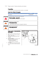


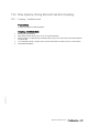


Engine mounts – Checking buffer
clearance
1. Take off protective cap (2).
2. Check marking (1):
• With marking 30: a = 3 mm +0,3 mm.
• With marking 40: a = 4 mm +0,3 mm.
3. Check dimension (a) with feeler gauge on
measuring groove (4).
4. If dimension (a) deviates from the above
specifications, adjust buffer clearance.
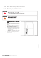
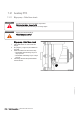
Engine mounts – Buffer clearance adjustment
1. Undo nut (3).
2. Adjust buffer clearance by turning the central buffer (1).
3. Coat mating face of nut (3) and thread of central buffer (1) with a little engine oil. Engine oil must not get
in contact with the rubber elements of the resilient mount.
4. Tighten nut (3) to the specified tightening torque securing the central buffer (1) to prevent it turning.
Name Size Type Lubricant Value/Standard
Nut M27 x 2 Tightening torque (Engine oil) 580 Nm +50 Nm
5. Fit protective cap (2).
176 | Task Description | M015412/03E 2012-02
TIM-ID: 0000007556 - 004