330-X02 Printer Operator’s Manual P/N 701333-004
ISSUE/REVISION SCHEDULE Comments Rev. No. Date Initial Release 701333-001 10/31/93 Technical Update 751206-001 03/31/94 Complete Reissue 701333-002 06/10/94 Technical Update 751206-001 09/15/94 Technical Update 756693-001 12/20/94 Complete Reissue 701333-003 02/02/96 Complete Reissue 701333-004 06/11/99 IBM is a registered trademark of IBM Corporation.
This equipment complies with FCC regulations for EMI. WARNING! This equipment generates, uses, and can radiate radio frequency energy, and, if not installed and used in accordance with the manual, may cause interference to radio communications. It has been tested and found to comply with the limits for a Class A computing device pursuant to Subpart J of Part 15 of FCC Rules, which are designed to provide reasonable protection against such interference when operated in a commercial environment.
Table of Contents Page Chapter 1. Introduction ............................................................................................ 1-1 Interfacing with the 1330 ................................................................................ 1-2 A-Coax Attachment ....................................................................................1-2 ASCII Attachment ......................................................................................1-3 Standard Features...........................
Table of Contents Page Operating Mode .......................................................................................... 3-2 Form Device ...............................................................................................3-2 Emulation Mode .........................................................................................3-2 Datastream Mode/Interface Type ................................................................3-3 Status Message ..............................................
Table of Contents Page Requesting a Host Application Program in SCS Mode .............................. 6-5 Halting a Print Operation in SCS Mode .....................................................6-5 Chapter 7. Maintaining the 1330.............................................................................. 7-1 Ventilation ....................................................................................................... 7-1 Cleaning the Printer ......................................................
Table of Contents Page Horizontal Tabbing Commands ............................................................... B-30 Vertical Movement Commands ............................................................... B-30 Vertical Tabbing Commands .................................................................... B-31 Page Formatting Commands ................................................................... B-32 Bit Image Graphics Commands ...............................................................
List of Illustrations Page Figure 2-1. Figure 2-2. Figure 2-3. Figure 2-4. Figure 2-5. Figure 2-6. Figure 2-7. Figure 2-8. Figure 2-9. Figure 2-10. Figure 2-11. Figure 2-12. Figure 2-13. Figure 2-14. Figure 2-15. Figure 2-16. Figure 2-17. Figure 2-18. Figure 2-19. Figure 2-20. Figure 2-21. Figure 2-22. Figure 2-23. Figure 3-1. Figure 3-2. Figure 4-1. Figure 5-1. Figure 7-1. Figure 7-2. Figure 7-3. Figure 7-4. Figure 7-5. Figure 7-6. Figure 7-7. Figure B-1. Figure B-2. Figure B-3. Figure B-4. Figure B-5.
Chapter 1. Introduction The MTX 1330 Printer is designed for high-volume printing and combines high reliability with convenient features such as modular paper handling, a 4-line, 80-character LCD that displays menus, an automatic forms thickness adjustment, and self-diagnostic messages. The 1330 produces clear, precise printing on up to six-part forms, accommodates continuous forms and cut sheet paper, and operates quietly for office environments.
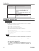
Introduction Attachment Boards Communication Environments Coax -3270 hosts and controllers with A-Coax adapters Coax/ASCII (Dual) -3270 hosts and controllers with A-Coax adapters -Mainframes, minicomputers (IBM AS400, etc.), workstations, and personal computers with Centronics parallel and RS232/RS432 serial interfaces Supports auto switching printer sharing between the 3270 and ASCII host. ASCII -Mainframes, workstations, minicomputers (IBM AS400, etc.
Introduction ASCII Attachment With an ASCII attachment, the following features are available on the 1330. Interfaces The following interfaces are software selectable from the front panel: • Centronics parallel • RS-232C • RS-422 Emulation The following printer emulations are available as standard features on the 1330 ASCII: • IBM Proprinter III and III XL • TI-810 modified Character Codes In ASCII mode, the American Standard Code for Information Exchange (ASCII) character set is recognized by the 1330.
Introduction Color The 1330 can print in monochrome or color, using an operator installable recirculating cloth ribbon cartridge. Two monochrome ribbons, a 4-color accent ribbon (black, red, blue, and green), and a subtractive 8-color ribbon (black, red, blue, green, yellow, magenta, cyan, and brown) are available. Paper Handling The 1330 comes standard with pull tractors for continuous forms feeding, and allows for easy paper loading at the front of the printer. Pinfeed forms from 3 to 14 inches (7.
Introduction • 3440 bytes • 3564 bytes The size can be selected by the operator during configuration. Self-Diagnostic Testing The 1330 has a self-diagnostic ability to ensure that the printer is in good working condition. If an error condition is encountered, the 1330 informs the operator by displaying an error message on the control panel. Should this occur, refer to the error message chart in Appendix A of this manual.
Introduction Forms Handler Module The Forms Handler module is operator installable in the front of the printer to vertically position forms. The module’s forms tractors are adjustable for two options: • Document on Demand (DOD) option – used for continuous forms • Document Insertion Device (DID) option – used for cut sheet/single sheet forms Printer Pedestal Stand The pedestal stand is designed so that the printer can be securely seated.
Chapter 2. Preparing to Operate the 1330 The 1330 printer has been designed for customer setup and preliminary check. Please read this chapter before you try to install or relocate your 1330. Inspecting the Package When the packaged 1330 printer arrives, inspect the carton for physical damage before unpacking it. If the carton is damaged, do not open it. Notify the Traffic Department or your sales representative, as appropriate. Also call the delivery carrier to request examination of the damage.
Preparing to Operate the 1330 Continuous Forms Module Feature Right End Cap Left End Cap Packing List Envelope Figure 2-1.
Preparing to Operate the 1330 Shipping Tube Figure 2-2. Foam Shipping Tube 9. The carriage on the 1330 is restrained by a foam shipping tube to prevent shifting during shipping. Before installing the printer, remove this tube, illustrated in Figure 2-2. Caution Failure to remove the carriage shipping tube before turning on the 1330 may result in damage to the printer.
Preparing to Operate the 1330 Installing the Ribbon Cartridge A monochrome ribbon cartridge is shipped with the 1330. Remember that if you have a monochrome ribbon installed, the 1330 will print in one color only. A multitrack color ribbon cartridge must be installed to allow printing in different colors. Ordering Ribbons You can use a Shifting ribbon or a Nonshifting ribbon in the 1330-X02. The ribbons have the same character life and for monochrome printing can be used interchangeably.
Preparing to Operate the 1330 Removable Corner Guides Ribbon Shifter Guide Ribbon Drive Gear Knob Ribbon Stop (REMOVE AFTER INSTALLATION) Mounting Clip Mounting Clip Figure 2-3. Shifting Ribbon Cartridge Ribbon Shifter Button Ribbon Shifter Button Platen Gap Lever Figure 2-4. Platen Gap Lever 5. If you are replacing the ribbon cartridge, grasp both sides of the ribbon shifter guide, as illustrated in Figure 2-5, and gently bend the sides toward the rear of the printer.
Preparing to Operate the 1330 Ribbon Shifter Guide Figure 2-5. Disengaging the Ribbon Shifter Guide 6. If you are replacing the ribbon cartridge, lift out the old cartridge and remove the plastic corner guides. Reinstall the new corner guides (they are packed in the new ribbon cartridge package) over the corner guide brackets. 7. Snap the new ribbon cartridge into place. Make sure that the tabs on the front and back of the cartridge snap into the slots on the ribbon cartridge bracket. 8.
Preparing to Operate the 1330 Installing a Nonshifting Ribbon Follow these steps to install or replace a Nonshifting ribbon cartridge. Refer to Figure 2-6. Note that the Nonshifting ribbon is monochrome only. 1. Turn the printer off and unplug the power cord from the outlet. 2. Raise the printer cover. 3. Set the platen gap lever away from the platen (toward you) as far as it will go (see Figure 2-4). Warning The print head may be hot. To move it, grasp the print head drive belt. 4.
Preparing to Operate the 1330 11. Snap the ribbon guide onto the print head. The ribbon guide must fit securely on the ribbon shifter buttons shown in Figure 2-4. Make sure the ribbon is not twisted. 12. Take up the ribbon slack by turning the ribbon advance knob in the direction of the arrow. Caution If the platen gap adjustment is set too close to the paper, the life of the print head will be reduced and the print head may be damaged. 13. Close the printer cover. 14.
Preparing to Operate the 1330 transformers, power distribution panels, and motors). The unit should not be installed where the atmosphere contains corrosive elements that may damage the unit. Cable runs should avoid areas that produce electromagnetic interference (for example, near transformers, switching equipment, power distribution panels, and under carpets where vacuum cleaning is done). Also, heavy equipment should not be moved or rolled over the cable.
Preparing to Operate the 1330 Connecting a Parallel or Serial Cable To comply with FCC regulations, use one of the following cables: • Parallel cable – MTX P/N 956588-001 (36-pin, 6 ft. EIA). • RS-232 serial cable – This is available as P/N 957520-010 (10 feet). For other RS-232 or RS-422 applications, use locally available cables. Before you connect the cable, make sure the Power switch is in the O (OFF) position.
Preparing to Operate the 1330 Powering on the 1330 Turn the printer on by setting the Power switch to the | (ON) position (see Figure 2-7). When the printer is powered on, BASIC ASSURANCE TEST IN PROGRESS will appear in the display window. The Basic Assurance Test (BAT) tests various components of the 1330 and ensures that the printer is ready for operation. The current status of the test in progress is displayed in the bottom row.
Preparing to Operate the 1330 Continuous Forms Module A Continuous DOD Option B Continuous DID Option B Single 14.0 in 35.6 cm 3.0 in 7.6 cm 14.0 in 35.6 cm 3.0 in 7.6 cm 14.0 in 35.6 cm 7.5 in 19.0 cm 15.0 in 38.1 cm 3.0 in 7.6 cm 15.0 in 38.1 cm 3.0 in 7.6 cm 15.0 in 38.1 cm 3.0 in 7.6 cm 0.006 in 0.15 mm 0.003 in 0.08 mm 0.006 in 0.15 mm 0.003 in 0.08 mm 0.006 in 0.15 mm 0.003 in 0.08 mm 0.025 in 0.64 mm 0.018 in 0.46 mm 0.025 in 0.64 mm 0.018 in 0.46 mm 0.025 in 0.64 mm 0.018 in 0.
Preparing to Operate the 1330 Continuous Forms Module DOD Option DID Option 15.0 in 38.1 cm 3.0 in 7.6 cm 15.0 in 38.1 cm 3.0 in 7.6 cm 15.0 in 38.1 cm 3.0 in 7.6 cm 14.0 in 35.6 cm 3.0 in 7.6 cm 14.0 in 35.6 cm 3.0 in 7.6 cm 14.0 in 35.6 cm 7.5 in 19.0 cm 0.65 in 1.7 cm 0.15 in 0.38 cm 0.65 in 1.7 cm 0.15 in 0.38 cm 0.65 in 1.7 cm 0.15 in 0.38 cm 0.25 in 0.64 cm 0.25 in 0.64 cm 0.25 in 0.64 cm First Print Line (E) 0.250 in 0.64 cm 0.625 in 1.59 cm 0.500 in 1.27 cm Last Print Line (F) 0.
Preparing to Operate the 1330 A C D E B F Figure 2-12.
Preparing to Operate the 1330 A C D E B F Figure 2-13.
Preparing to Operate the 1330 Review the following points carefully to ensure that your forms are appropriate for use in the 1330. 1. Except for horizontal dimensions of the first print position specified in Figures 2-12 and 2-13, no printing should occur within 0.25 inch (0.6 cm) of any edge, perforation, or fold. 2. Printing must not occur across any holes, perforations, or edges of the forms, nor should printing occur directly on the platen. 3. Continuous card stock forms are not recommended. 4.
Preparing to Operate the 1330 Installing the Forms – Continuous Forms Module Forms are fed into the 1330 through the slot in the front of the printer, and exit out the rear slot in the top, as illustrated in Figure 2-14. Open for Top Paper Exit Module Flap Front Slot Optional Stand Figure 2-14. Paper Feed Slots To install the forms, follow these steps: 1. If the printer is powered on, press the Stop key to place the 1330 in Stop mode. 2. Raise the printer cover. 3. Open the tractor doors.
Preparing to Operate the 1330 Figure 2-15. Open Tractor Door 4. If the right forms tractor has not been adjusted for the paper width, loosen the tractor by flipping the lever up, as illustrated in Figure 2-16. (Note that the left tractor cannot be adjusted.) Figure 2-16. Flipping the Tractor Lever 5. Insert the paper through the front slot (see Figure 2-17). Continue hand feeding the paper until the top of the paper appears flush with the top of the tractors. 6.
Preparing to Operate the 1330 Figure 2-17. Inserting Paper - Continuous Forms Module 7. Raise the module flap and position the paper so the pinfeed holes along the edge of the paper fit evenly over the tractor pins. Slide the tractor, if necessary, to adjust for the paper width. 8. When there is no slack in the paper, and it is aligned evenly, close the tractor doors. 9. Flip the tractor lever down to lock it in place, referring to Figure 2-16. 10.
Preparing to Operate the 1330 Setting the Platen Gap Lever The platen gap lever, located on the carriage to the left of the print head (see Figure 2-18), should be set according to the thickness of the forms being used. Platen Gap Lever Figure 2-18. Platen Gap Lever To maximize print head life and performance, follow these instructions for setting the platen gap lever when you reload forms: For Single Part Forms 1.
Preparing to Operate the 1330 3. If the print quality is not acceptable after you adjust the platen gap lever, refer to “Checking Character Width and Print Registration” in Chapter 7. Caution If the platen gap lever is set too close to the paper, the life of the print head will be reduced and the print head may be damaged. The platen gap lever must be far enough from the platen to allow the shifter nosepiece to rotate smoothly, and to ensure that the forms are not smudged by the ribbon.
Preparing to Operate the 1330 7. Move the right tractor to the approximate width of the forms you plan to use. Note that three standard widths for computer pinfeed paper – 8 1/4 inches (21.0 cm), 9 1/2 inches (24.1 cm), and 14 7/8 inches (37.8 cm) – are marked on the module. 8. Center the paper supports (Figure 2-19) an equal distance from the tractors and from each other. For narrow forms, you can snap out the paper supports. 9. Open the doors of both forms tractors. 10.
Preparing to Operate the 1330 drive. The bars will snap into the OFF position, as shown in Figure 2-20. Roller Drive Shown OFF Paper Supports Slide Bar Slide Bar Figure 2-20. DOD Option with Roller Drive Next is the procedure for using the Document Insertion Device (DID) option. Installing Forms Using the DID Option Refer to Figure 2-21 for a picture of the Forms Handler module set for the DID option.
Preparing to Operate the 1330 3. Unlock the left forms tractor of the module. 4. Slide the left forms tractor to the left, as far as it will go. 5. Lock the left tractor. 6. Unlock the right forms tractor on the module. 7. Insert a sample of the forms you plan to use into the module slot, making sure that the left edge of the forms is in contact with the left inside edge of the module. 8. Move the right tractor so that the arrow on the bottom of the tractor points to the right edge of the forms.
Preparing to Operate the 1330 15. Open the printer cover. 16. Adjust the setting of the platen gap lever, as necessary. Move the lever to a lower setting (toward the platen) for darker print; move the lever to a higher setting (toward you) for lighter print. If you are using multipart forms, make sure that the last copy is legible without any smudging on any other copy. If the last copy is too light, move the lever to a lower setting.
Chapter 3. Operator Control Panel The 1330 Operator Control Panel, located on the front of the printer, consists of the status display window and the keypad. The status display monitors printer operations, and the keypad is used to start and control operator functions. See Figure 3-1. Start Stop Load/ Eject Top of Form Form Feed Line Space Option Contrast Setup Save Cancel Print Figure 3-1.
Operator Control Panel Cu In 3270 mode or share mode, the Cu signal displays when the 1330 is in communication with the controller. If the printer is receiving data, the Cu signal will blink. S/C/A The one-letter display indicates the current interface mode the printer is configured with. The valid displays for the interface option are “S” (share), “C” (3270), and “A” (ASCII). Operating Mode The 1330 has four types of operation modes: Start, Stop, Menu, and Contrast.
Operator Control Panel Datastream Mode/Interface Type When host data is being processed, the type of datastream will be displayed in this location. The acceptable datastreams are LU1 (SCS), LU3 (DSC/DSE), LU1-IPDS, and LU3IPDS. In ASCII, the interface type will be displayed. Those types can be parallel, RS232, RS-422, or ASC. Status Message The 1330 displays the current printer status in this location. When the 1330 is operated under normal conditions, no message should be displayed.
Operator Control Panel Load/ Eject With the Document Insertion Device, pressing the Load/Eject key at initial load will advance the paper to the current position on the form. Pressing the key again will eject the paper. With the Document on Demand device, pressing the Load/Eject key in Ready mode for initial load will advance the paper to the first print line.
Operator Control Panel Option The Option key puts the 1330 in Menu mode. In Menu mode you can configure the 1330 by setting options to the values you want or you can run diagnostic tests to verify the printer’s performance. This key is active only in Stop mode. Save The Save key is only active in Menu mode. It saves the value of the currently selected option when you are configuring the 1330 from the keypad. The Save key is also used to start a test case under the Diagnostic menu.
Chapter 4. Configuring the 1330 in 3270 Mode The configuration process enables you to customize the 1330 to meet your specific operating needs without assistance from Customer Service. You can also change configuration parameters at any time without service costs. The 1330 Operator Control Panel provides access to the configuration options. Now that you are familiar with the operator control panel, you are ready to configure the printer.
Configuring the 1330 in 3270 Mode 3. If the optional dual interface board is installed in your printer, the status display will give you the option of pressing the Start key for the 3270 menu or pressing the Stop key for the ASCII menu. At this point you may select one of the two menus to enter or press the Cancel key to quit and return the printer to the Ready mode. 4. You are now in the Menu mode.
701333-004 300 Compatibility 400 Printer Setup 600 Attachment 700 Extended Keypad 800 Program Symbol Diagnostic 901 Serial Number 902 Device Specification Information 900 Vital Product Data 801 Programmed Symbols 802 Reserved for future use 803 Reserved for future use 804 APA Print Direction 701 Print Configuration 702 Quick Reference 703 Set Factory Default 704 POR Custom Set 705 Save Cust Set 706 Recall Cust Set 707 Display Character Count 708 PA1 709 PA2 710 Buffer Reprint 601 Interface 602 Idle
Configuring the 1330 in 3270 Mode Selecting a Menu Option When the target menu appears on the first line of the status display, you can get into that option and configure the printer by changing the value of that option. Follow these steps: 1. To select an option, press the Start key when the option you want to change appears on the second line of the status display. Once an option is selected, the originally saved value of that option will appear on the third line of the status display. 2.
Configuring the 1330 in 3270 Mode The Configuration Options The chart on Page 4-3 provides you with a list of the configuration options for the 1330 in 3270 mode. This section defines the options in each menu. 100 Page Format The following options define the printer’s page format. 101 – Left Margin Configuration Option 101 enables you to specify a left margin value for LU3 mode. This value is the first possible print position. Valid values are 1 through 20. The default is 1.
Configuring the 1330 in 3270 Mode 102 – Characters per Inch (CPI) Use Configuration Option 102 to specify the number of characters per inch that the 1330 will print. Option Choice 102 Note: Meaning 1 10 CPI (default) 2 12 CPI 3 15 CPI 4 16.7 CPI 5 17.1 CPI 6 20 CPI When you select 16.7 CPI or 20 CPI, the printing defaults to Data Processing (draft) quality. To specify your choice, follow the configuration procedure that begins on Page 4-1.
Configuring the 1330 in 3270 Mode 104 – Maximum Print Position (MPP) Configuration Option 104 enables you to specify a maximum print position (MPP) value. This value is the print position of the last character on the print line. The MPP range is based on the following MPP-CPI chart. Valid values are 1 through the value shown in the chart for each CPI. The default is 132. MPP CPI 132 10 158 12 198 15 220 16.7 225 17.
Configuring the 1330 in 3270 Mode 107 – Force Set Media Size With Configuration Option 107, in IPDS mode, you can choose to unconditionally honor the Set Media Size command. If you choose 0 (disable), the page size will be the smaller of the operator panel settings and the Set Media Size values.
Configuring the 1330 in 3270 Mode Option Choice 201 18 19 20 21 22 23 24 25 26 27 28 29 30 31 32 33 34 35 36 37 38 39 40 Meaning International Set 5 International Set 1 Japanese Katakana Portuguese Swiss Bilingual French Azerty 105 Canadian French Canadian Bilingual Arabic Hebrew BLT (IBM 4224-compatible) Hebrew New Hebrew Old Thai Turkish OCR-A OCR-B Icelandic Latin/ROECE Cyrillic New Greek Old Greek Yugoslav Line Drawing To select a language character set, follow the configuration procedure that begi
Configuring the 1330 in 3270 Mode 203 – Mono/Dual Case Configuration Option 203 enables you to specify whether the 1330 will print in mono case (all characters uppercase) or dual case (characters uppercase and lowercase) in LU3 mode. Option Choice 203 Meaning 1 Mono case – all characters are printed in uppercase 2 Dual case – characters are printed as sent in uppercase and lowercase (default) To specify your choice, follow the configuration procedure that begins on Page 4-1.
Configuring the 1330 in 3270 Mode 206 – Print Quality With Configuration Option 206, you can choose print quality. Option 206 Choice Meaning 1 Data processing (DP) quality (default) 2 Data processing text (DP text) quality 3 Near letter quality (NLQ) 4 Fast draft (FD) To select the print quality, follow the configuration procedure that begins on Page 4-1. Enter your choice by pressing the appropriate number key (1, 2, 3, or 4), or you can keep the current print quality by pressing Save.
Configuring the 1330 in 3270 Mode 209 – Dotted Zero Use Configuration Option 209 to specify whether a dotted zero should be printed when a zero is selected. If you specify NO, the dotted zero will not be used. Option 209 Choice Meaning 0 (No) The dotted zero will not be used (default) 1 (Yes) The dotted zero will be used To specify your choice, follow the configuration procedure that begins on Page 4-1. Enter your choice (0 or 1) and press Save.
Configuring the 1330 in 3270 Mode 300 Compatibility The following options define the printer’s compatibility. 301 – Carriage Return (CR) at MPP + 1 Configuration Option 301 allows you to choose whether the printer will do a carriage return (CR) after the maximum print position (MPP) of a print line has been exceeded.
Configuring the 1330 in 3270 Mode 304 – Form Feed (FF) Use Configuration Option 304 to specify if the 1330 will perform a form feed (FF) operation before or after a local print, after an LU3 print, or never. Option 304 Choice Meaning 1 No FF follows print (No FF added to LU3 print) (default) 2 FF after local print 3 FF after LU3 print 4 FF before local print 5 FF before and after local print To specify your choice, follow the configuration procedure that begins on Page 4-1.
Configuring the 1330 in 3270 Mode 307 – Form Feed (FF) Printed with a Space Use Configuration Option 307 to specify whether the print head will move to the first character position or second character position on the next top of form (TOF). Option 307 Choice Meaning 0 (No) Puts the print head at TOF, character 1 1 (Yes) Puts the print head at TOF, character 2 (default) To specify your choice, follow the configuration procedure that begins on Page 4-1. Enter your choice (0 or 1) and press Save.
Configuring the 1330 in 3270 Mode This option shall not have any effect in IPDS bar code printing. To specify the bar code control default, follow the configuration procedure that begins on Page 4-1. Enter your choice (1, 2, or 3) and press Save. 310 – Base Color Use Configuration Option 310 to specify whether the base color of the printed text defaults to green or black when you power on the printer. The controller can override the operator field attribute enable/disable setting.
Configuring the 1330 in 3270 Mode Option 311 Choice Meaning 0 Normal operation (default) 1 Bolding 2 Underscore To specify your choice, follow the configuration procedure that begins on Page 4-1. Enter your choice (0, 1, or 2) and press Save. 312 – Ignore SCS Commands When enabled, Configuration Option 312 will cause the printer to ignore the Set Line Density and the Set Page Density commands.
Configuring the 1330 in 3270 Mode If you choose an operator selected print format for Option 401, the last value saved for each parameter becomes the new default value when the printer is powered on. Option 401 Choice Meaning 1 Default format 2 Operator selected format (default) To specify your choice, follow the configuration procedure that begins on Page 4-1. Enter the your choice (1 or 2) and press Save.
Configuring the 1330 in 3270 Mode Before specifying the print head style, turn the printer off. Refer to the label on the print head to determine which style of print head is installed. If you are installing a new print head, see “Replacing the Print Head” in Chapter 7 of this manual for instructions. After you have determined the style of print head currently in use, turn the 1330 back on. To inform the printer of the print head style, follow the configuration procedure that begins on Page 4-1.
Configuring the 1330 in 3270 Mode Option 406 Choice Meaning 0 Use ribbon type sensor – no override (default) 1 Override ribbon type – accent (4-color) ribbon 2 Override ribbon type – subtractive (8-color) ribbon 3 Override ribbon type – monochrome ribbon In normal operation, the default should be used. The other choices enable the printer to be used with a faulty ribbon or ribbon sensor. The other choices are not recommended unless the ribbon or sensor is faulty.
Configuring the 1330 in 3270 Mode 409 – Auto Eject To make it easy for you to tear off forms, configuration Option 409 enables you to have an automatic form eject after the 1330 has been idle in DOD mode for an operator selectable time period. After additional data is received, the form will be retracted. If you choose 0 (Disabled), the auto eject will not function.
Configuring the 1330 in 3270 Mode 412 – Horizontal Offset Use Configuration Option 412 to set the first printable position on the page. Values range between 0 and 127. Units are in increments of 0.007 inch (0.02 cm), so the offset is between 0 and 0.88 inch (0 to 2.24 cm). The default is 14. To specify your choice, follow the configuration procedure that begins on Page 4-1. Enter your choice (from 0 to 127) and press Save.
Configuring the 1330 in 3270 Mode Option 415 Choice Meaning 0 (No) The paper out sensor is disabled 1 (Yes) The paper out sensor is enabled (default) To specify your choice, follow the configuration procedure that begins on Page 4-1. Enter your choice (0 or 1) and press Save. 416 – Paper Skew Sensor Enable Use Configuration Option 416 to enable or disable the paper skew sensor. If you specify NO (by entering 0), the paper skew sensor will be disabled.
Configuring the 1330 in 3270 Mode Note that you will only be able to access the option that corresponds to the device you have in the printer; that is, if you have a DID device, the menu will only allow you to access the DID Load Adjust option. Loads can be initiated in Stop or Ready mode with a DID device, but only in Ready mode with a DOD device. 420 – Stop Mode Timeout (TO) Configuration Option 420 enables you to select what the 1330 will do when it has been in Stop mode for more than 10 minutes.
Configuring the 1330 in 3270 Mode 423 – Report Intervention Configuration Option 423 enables you to set the 1330 so that interventions are or are not reported to the host. Option Choice 423 Meaning Yes The 1330 reports interventions to the host (default) No The 1330 does not report interventions to the host To specify your choice, follow the configuration procedure that begins on Page 4-1. Enter your choice (Yes or No) and press Save.
Configuring the 1330 in 3270 Mode 502 – Buffer Size Configuration Option 502 lets you select the effective size of the display screen from these options: Option Choice 502 Meaning 1 1920-byte display screen (default) 2 2560-byte display screen 3 3440-byte display screen 4 3564-byte display screen To select the screen size, follow the configuration procedure that begins on Page 4-1.
Configuring the 1330 in 3270 Mode 600 Attachment The following options define printer attachment. 601 – Interface Configuration Option 601 enables you to manually select the 3270 or ASCII interface from the dual interface card when installed in the 1330 printer.
Configuring the 1330 in 3270 Mode 700 Extended Keypad The following options define the extended keypad. 701 – Print Configuration Use Configuration Option 701 to print a list of the current configuration values. To print this list, follow the configuration procedure that begins on Page 4-1. 701 PRINT CONFIG will appear in the status window. Press the Save key. The printer will print a list of option numbers, followed by their current values. See Figure 4-2 for a sample configuration value printout.
Configuring the 1330 in 3270 Mode PRINTER TYPE: 1330/6573-X RELEASE LEVEL: PC 01 MC 01 IO 01 PATCH LEVEL: 02 00 01 26A1 FC24 RAM: A0000 CHECKSUMS: DUAL INTERFACE BOARD INSTALLED CFD MODULE SUBTRACTIVE RIBBON 3270 CONFIGURATION *** PAGE FORMAT *** 101 LEFT MARGIN 102 CPI 103 LPI 104 MPP 105 FORM LENGTH 106 LINE SPACING 107 SET MEDIA 01 1(10) 1 (6) 132 66 1 Single 0 Disable *FONT & PRT QUALITY* 201 LANGUAGE 202 DISPLAY LANG 203 CASE 204 BOLD PRINT 205 BIDIR 2 PAS PRT 206 PRINT QUALTY 207 HOS
Configuring the 1330 in 3270 Mode 307 FF PRNT W/SPACE 1 Yes 308 309 310 311 312 FORMATTED PRINT BAR CODE CONTROL BASE COLOR ATTRIB HIGHLIT IGN SCS CMDS 0 1 1 0 0 Ignr NL/CR/EM Standard Black Enable No Highlight Disable *** PRINTER SETUP *** 401 OPERATOR FORMAT 402 KEY ALARM 403 ALARM ON ERROR 404 PRNT HEAD STYL 405 PRT HD COL SPAC 406 RIBBON TYPE 407 RB TRAK SEL ADJ 408 MODULE TYPE 409 AUTO EJECT 410 FULL FF EJECT 411 EJECT ADJUSTMENT 412 HORZ OFFSET 413 HORZ REGSTRN 414 PAPER JAM 415 PAPER OUT 416
Configuring the 1330 in 3270 Mode 702 – Quick Reference Use Configuration Option 702 to print all possible option values associated with each option. 703 – Set Factory Defaults Configuration Option 703 is used to reinitialize the nonvolatile RAM (NVRAM).
Configuring the 1330 in 3270 Mode 705 – Save Custom Set Configuration Option 705 specifies which custom set you will immediately copy the current set into. Parameters (such as CPI, LPI, and so on) that you changed during a print job can be saved into one of these custom sets and recalled later when required. Option 705 Choice 1–4 Meaning Custom set 1 through 4 To use this option, follow the configuration procedure that begins on Page 4-1.
Configuring the 1330 in 3270 Mode 708 – PA1 Configuration Option 708 is used for special applications. Refer to “Requesting a Host Application Program in SCS Mode” in Chapter 6 of this manual. In Stop mode, press the Option key. Follow the configuration procedure that begins on Page 4-1 to bring up this option. The status window will display PA1. Pressing the Save key will send a message to the host or controller. If the message to the controller is pending, the printer will display PA1 RESPONSE.
Configuring the 1330 in 3270 Mode 804 – APA Print Direction Configuration Option 804 chooses either unidirectional or bidirectional printing for All Points Addressable (APA) Programmed Symbols and some bar codes. Unidirectional printing improves dot registration. Bidirectional printing is faster, but a degradation in print registration may occur.
Chapter 5. Configuring the 1330 in ASCII Mode The configuration process enables you to customize the 1330 to meet your specific operating needs without assistance from Customer Service. You can also change configuration parameters at any time without service costs. The 1330 Operator Control Panel provides access to the configuration options. Now that you are familiar with the operator control panel, you are ready to configure the printer.
Configuring the 1330 in ASCII Mode 4. You are now in the Menu mode. You will see the first menu of the menu list displayed on the first line of the status display and the first option of that menu displayed on the second line of the status display. There may be some abbreviation of the menu name or its option in order to make it fit on the 20-character display.
701333-004 300 Compatibility 301 Vertical Tab Setup 302 DEF HT (810) 303 Define CR 304 Define LF 305 PERF Skip 306 Ignore Screen 307 Bit Graphics (Proprinter) 308 BC Space CHR (ANSI) 309 Bar Code Control 200 Font & Print Quality 201 Language 202 Display Language 203 Mono/Dual Case 204 Bold Print 205 Bidir 2 Pass Prt 206 Print Quality 101 Left Margin 102 CPI 103 LPI 104 MPP 105 Form Length 106 Line Spacing 100 Page Format 600 Attachment Diagnostic 701 Print Configuration 702 Quick Reference 703 Set F
Configuring the 1330 in ASCII Mode Selecting a Menu Option When the target menu appears on the first line of the status display, you can get into that option and configure the printer by changing the value of that option. Follow these steps: 1. To select an option, press the Start key when the option you want to change appears on the second line of the status display. Once an option is selected, the originally saved value of that option will appear on the third line of the status display. 2.
Configuring the 1330 in ASCII Mode The Configuration Options The chart on Page 5-3 provides a list of the configuration options for the 1330 in ASCII mode. This section defines the options in each menu. 100 Page Format The following options define the printer’s page format. 101 – Left Margin Configuration Option 101 enables you to specify a left margin value. This value is the first possible print position. Valid values are 1 through 20. The default is 1.
Configuring the 1330 in ASCII Mode 103 – Lines per Inch (LPI) Use Configuration Option 103 to specify the lines per inch that the 1330 prints. Option 103 Choice Meaning 1 6 lines per inch (default) 2 8 lines per inch 3 144 lines per inch (for testing purposes only) To specify your choice, follow the configuration procedure that begins on Page 5-1. Enter your choice (1, 2, or 3) and press Save. Note: For printing at 3 LPI or 4 LPI, refer to Option 106.
Configuring the 1330 in ASCII Mode 105 – Form Length Use Configuration Option 105 to specify the number of lines per page that the 1330 prints. Valid values are 1 through 127. The default setting is 66. To specify the forms length, follow the configuration procedure that begins on Page 5-1. You can enter a different value, or keep the current value by pressing Save.
Configuring the 1330 in ASCII Mode Option 201 Choice Meaning 1 PC Character Set (default)(Code Page 437) 2 PC Multilingual (Code Page 850) 3 ASCII - EBCDIC (Code Page 437 modified) 4 810 – Katakana 5 OCR-A ASCII (Code Page 340) 6 OCR-A EBCDIC (Code Page 892) 7 OCR-B ASCII (Code Page 340) 8 OCR-B EBCDIC (Code Page 893) 9 Hebrew A (Code Page 862)(PC Char Set 2) 10 Hebrew B (Code Page 862 modified)(PC Char Set 2) 11 Hebrew C (Code Page 862 modified) 12 PC Character Set 2 Note: Lang
Configuring the 1330 in ASCII Mode 203 – Mono/Dual Case Use Configuration Option 203 to specify whether the 1330 prints in mono case (all characters uppercase) or dual case (characters uppercase and lowercase). Option 203 Choice Meaning 1 Mono case – all characters are printed in uppercase 2 Dual case – characters are printed as sent in uppercase and lowercase (default) To specify your choice, follow the configuration procedure that begins on Page 5-1. Enter your choice (1 or 2) and press Save.
Configuring the 1330 in ASCII Mode 206 – Print Quality With Configuration Option 206, you can choose between three print qualities, data processing, data processing text, or near letter quality. Option 206 Choice Meaning 1 Data processing (draft) quality (default) 2 Data processing text (DP text) quality 3 Near letter quality (NLQ)(not at 20 CPI) To select the print quality, follow the configuration procedure that begins on Page 5-1.
Configuring the 1330 in ASCII Mode 302 – Define Horizontal Tab (810) Use Configuration Option 302 to specify if the 1330 will perform a horizontal tab in TI810 mode, either as a TI-810 specified horizontal tab or as an IBM Proprinter specified horizontal tab. Option 302 Choice Meaning 0 HT = TI-810 horizontal tab (default) 1 HT = Proprinter horizontal tab To specify your choice, follow the configuration procedure that begins on Page 5-1. Enter your choice (0 or 1) and press Save.
Configuring the 1330 in ASCII Mode 305 – Automatic Perforation Skip Use Configuration Option 305 to specify whether or not the printer automatically skips a form perforation. If this option is enabled, the printer skips three lines at the end of each page. Option Choice 305 Meaning 0 Disable automatic perforation skip (default) 1 Enable automatic perforation skip To make your choice, follow the configuration procedure that begins on Page 5-1.
Configuring the 1330 in ASCII Mode 308 – BC Space CHR Configuration Option 308 enables and disables the processing of the ANSI Space character as an actual bar code character. With this Option disabled, the ANSI Standard rules apply to the processing of Space characters. With this Option enabled, the ANSI Space character is processed as an actual bar code character and the ANSI comma character serves as a bar code separator as well as a space character to move the print position one space to the right.
Configuring the 1330 in ASCII Mode 400 Printer Setup The following options define the printer setup. 401 – Save Operator Format Configuration Option 401 lets you specify a default print format or an operator selected print format. The 1330 normally powers on with all printer format parameters set to their front panel values. However, you can specify that the 1330 power on with the default printer format values.
Configuring the 1330 in ASCII Mode To specify your choice, follow the configuration procedure that begins on Page 5-1. Enter your choice (0 or 1) and press Save. 403 – Alarm on Error Use Configuration Option 403 to specify whether a beep sounds when an error occurs. If you specify NO (by entering 0), the alarm does not sound.
Configuring the 1330 in ASCII Mode be aligned vertically, Option 405 can be used to correct this condition. Valid values range from 90 to 100. The default is 95. Refer to “Checking Character Width” in Chapter 7 for complete instructions. • • • • • • • • • • • • • • • • Correct Incorrect Figure 5-1. Aligned and Unaligned Dots in Characters 406 – Ribbon Type Override Configuration Option 406 enables you to override the type of ribbon installed in the printer.
Configuring the 1330 in ASCII Mode 408 – Module Type Override Use Configuration Option 408 to override the type of forms module installed in the printer. Enter 0 to disable the override and use the module sensor or enter 1, 2, or 3 to override the Document Insertion Device (DID) option, the Document on Demand (DOD) option, or the Continuous Forms module.
Configuring the 1330 in ASCII Mode Option 410 Choice Meaning 00 Return automatically with no warning when the next print is ready for processing 1-255 The number of seconds to wait after the next print is ready for processing before automatically returning to the next print position (default = 5 seconds) To specify your choice, follow the configuration procedure that begins on Page 5-1. Enter your choice and press the Save key.
Configuring the 1330 in ASCII Mode 413 – Horizontal Registration Configuration Option 413 enables you to adjust the printed line horizontally for vertical character alignment. Values range from 0 through 255. The default setting is 127. Units are in increments of 0.0007 inch (0.002 cm). This option is used with bidirectional printing only. For complete instructions, refer to “Checking Print Registration” in Chapter 7. To specify your choice, follow the configuration procedure that begins on Page 5-1.
Configuring the 1330 in ASCII Mode 416 – Paper Skew Sensor Enable Use Configuration Option 416 to enable or disable the paper skew sensor. If you specify NO (by entering 0), the paper skew sensor is disabled. Note: Paper skew is checked only when the Forms module is in DID mode. Option 416 Choice Meaning 0 (No) The paper skew sensor is disabled 1 (Yes) The paper skew sensor is enabled (default) To specify your choice, follow the configuration procedure that begins on Page 5-1.
Configuring the 1330 in ASCII Mode 421 – Operator Panel Adjust Use Configuration Option 421 to adjust the intensity of the LCD on the Operator Panel. The intensity ranges from light to dark. Option 421 Choice Meaning 1 Light 2 Normal (default) 3 Dark To specify your choice, follow the configuration procedure that begins on Page 5-1. Enter your choice (1, 2, or 3) and press Save.
Configuring the 1330 in ASCII Mode 500 Communication The following options define the printer’s communication selections. 501 – Printer Emulation Mode Configuration Option 501 selects the printer emulation. Option 501 Choice Meaning 1 Proprinter (default) 2 TI-810 3-5 Reserved To specify your choice, follow the configuration procedure that begins on Page 5-1. Enter your choice and press the Save key. For a listing of the commands supported in each emulation, refer to Appendix B of this manual.
Configuring the 1330 in ASCII Mode To specify your choice, follow the configuration procedure that begins on Page 5-1. Enter your choice and press the Save key. 504 – Baud Rate Configuration Option 504 selects the printer baud rate. The printer baud rate must match that of the host. Option 504 Choice Meaning 1 56K (RS-422 only) 2 38.4K (RS-422 only) 3 19.
Configuring the 1330 in ASCII Mode 506 – Data Bits Configuration Option 506 selects 7-bit or 8-bit data. This selection must match that of the host. Option 506 Choice Meaning 1 Select 7-bit data (default) 2 Select 8-bit data To specify your choice, follow the configuration procedure that begins on Page 5-1. Enter your choice and press the Save key. 507 – Stop Bits Configuration Option 507 selects one or two stop bits. This selection must match that of the host.
Configuring the 1330 in ASCII Mode 509 – Handshaking Configuration Option 509 controls host-printer handshaking. Option 509 Choice Meaning 1 XON/XOFF – send XOFF to host to stop sending (default) 2 Busy to DTR – indicate online and not busy on DTR line 3 Reverse channel – indicate busy on interface connector pin 11 4 None – used for troubleshooting interface, not normally used To specify your choice, follow the configuration procedure that begins on Page 5-1.
Configuring the 1330 in ASCII Mode 600 Attachment The following options define the printer’s attachment selections. 601 – Interface Configuration Option 601 enables you to manually select the 3270 or ASCII interface from the dual interface card when installed in the 1330 printer.
Configuring the 1330 in ASCII Mode Note: A value of 0 seconds means that if the printer is in the mode indicated by the option or when it enters that mode, it will remain in that mode until this option is changed to a nonzero value or until power is cycled. 603 – Interface Type Configuration Option 603 selects the interface type. Option Choice 603 Meaning 0 Parallel (default) 1 RS-232 2 RS-422 To specify your choice, follow the configuration procedure that begins on Page 5-1.
Configuring the 1330 in ASCII Mode PRINTER TYPE: 1330/6573-X RELEASE LEVEL: PC MC 01 IO 01 01 PATCH LEVEL: 02 00 01 26A1 FC24 RAM: A0000 CHECKSUMS: DUAL INTERFACE BOARD INSTALLED CFD MODULE SUBTRACTIVE RIBBON ASCII CONFIGURATION *** PAGE FORMAT *** 101 LEFT MARGIN 102 CPI 103 LPI 104 MPP 105 FORM LENGTH 106 LINE SPACING 01 1(10) 1 (6) 136 66 1 Single *FONT & PRT QUALITY* 201 LANGUAGE 202 DISPLAY LANG 203 CASE 204 BOLD PRINT 205 BIDIR 2 PAS PRT 206 PRINT QUALTY 01 0 2 0 2 1 PC Char Set En
Configuring the 1330 in ASCII Mode *** PRINTER SETUP *** 401 OPERATOR FORMAT 402 KEY ALARM 403 ALARM ON ERROR 404 PRNT HEAD STYL 405 PRT HD COL SPAC 406 RIBBON TYPE 407 RB TRAK SEL ADJ 408 MODULE TYPE 409 AUTO EJECT 410 AUTO RETURN ADJ 411 EJECT ADJUSTMENT 412 HORZ OFFSET 413 HORZ REGSTRN 414 PAPER JAM 415 PAPER OUT 416 PAPER SKEW ** COMMUNICATION ** 501 PRINTER EMULTN 502 BUFFER SIZE 503 DC1 / DC3 504 BAUD RATE 505 PARITY 506 DATA BITS 507 STOP BITS 508 MODEM CONTROL 509 HANDSHAKING 510 (RESERVED) 511 RS4
Configuring the 1330 in ASCII Mode 702 – Quick Reference Use Configuration Option 702 to list all possible option values associated with each option. 703 – Set Factory Defaults Configuration Option 703 is used to reinitialize the nonvolatile RAM (NVRAM).
Configuring the 1330 in ASCII Mode 705 – Save Custom Set Configuration Option 705 specifies which custom set you will immediately copy the current set into. Option Choice 705 1–4 Meaning Custom set 1 through 4 To use this option, follow the configuration procedure that begins on Page 5-1. 706 – Recall Custom Set Configuration Option 706 specifies which custom set you will immediately recall as the current set. A soft POR will occur when you exit this option.
Chapter 6. Operating the 1330 Operating procedures for the 1330 can be divided into three categories: • Setting the print format • Specific operating procedures • General operating procedures Setting the Print Format The print format consists of four parameters: characters per inch, line length (maximum print position), forms length, and vertical line density. The following points explain 1330 print format: • The number of characters per inch (CPI) can be selected by using Configuration Option 102.
Operating the 1330 If no operator set values have been saved for the print format settings, that is, choice 2 has been saved for Configuration Option 401 (see Chapter 4), the 1330 assumes the following default values: Function Default Characters Per Inch 10 Line Length 132 (136 for ASCII) Forms Length 66 Lines Per Inch 6 LPI The following sections describe the procedures for setting each print format parameter for the 1330.
Operating the 1330 Adjusting the Top of Form Position Once you have printed the setup line, you can visually verify the top of form position, as well as the left and right margins of the print line. If you want to fine adjust the top of form position, follow these steps: 1. Press Stop to place the 1330 in Stop mode. 2. Press the Form Feed key to advance the forms to the next top of form position. 3. To fine adjust the top of form position, press the Up Arrow key or Down Arrow key.
Operating the 1330 • ASCII Modem Control • ASCII IRC • ASCII Buffer Size • ASCII Recognize DC1/DC3 • ASCII Parity • ASCII Stop Bits • ASCII Handshaking • ASCII RS-422 Invert These options will stay in effect for the printer no matter which custom set you are using. For the remaining option settings, you can save them to one of four available custom sets by using Option 705, Save Custom Set. Any custom set may be recalled at any time by using Option 706, Recall Custom Set.
Operating the 1330 To reprint the print buffer, follow these steps: 1. Press Stop to place the 1330 in Stop mode. 2. Correct any problems that need attention. 3. Press Form Feed to advance the forms to the first line of the next page. 4. Go to Buffer Reprint (Option 710) and press Save. 5. To return to Start mode and resume printing, exit Option mode and press the Start key. Note: In SCS operations, the buffer cannot be reprinted.
Chapter 7. Maintaining the 1330 Maintenance procedures for the 1330 include allowing adequate ventilation, cleaning the printer, replacing and changing the print head as necessary, and adjusting the print registration as required. Ventilation Inadequate ventilation of the 1330 may result in overheating, which can damage the printer. Make sure that the vents are kept clean and free of obstructions, and that there is at least six inches (15 cm) of clearance on each side of the printer.
Maintaining the 1330 To order a print head kit for the 1330, contact your MTX sales representative. Use the following part number: 953567-001. Note: When the 1330 has been printing for an extended time, the print head may occasionally slow down, start printing unidirectionally, and pause at the end of each line. This is not a sign of excessive wear. These conditions occur automatically as a preventive measure when the temperature of the print head exceeds the normal operating level.
Maintaining the 1330 Connectors Figure 7-1. Replacing the Print Head Note: Print head style 2 has a connector at the top of the print head. This connector does not have to be disconnected when you remove the print head. Note: Take care that the wiring from the ribbon select motor stays through the carriage restraining hook. Refer to Figure 7-2. 10. If it is installed, remove the tie-wrap holding the print head wires to the carriage. Restraining Hook Figure 7-2.
Maintaining the 1330 11. Remove the mounting screws on each side of the print head with the hex key provided with the replacement print head. See Figure 7-3. Remove the print head by carefully pulling it straight up. Mounting Screws Figure 7-3. Mounting Screws 12. Refer to the label on the print head to determine the style of the replacement print head you are installing (style 1 or style 2). 13. To install the new print head, reverse the print head removal procedure. 14.
Maintaining the 1330 Caution Failure to enter the correct print head style under Configuration Option 404 can result in poor print head performance and can damage the print head. 22. Press the Save key and the Stop key. If you plan to print in data processing quality, enter 1. If you want to print in data processing text quality, enter 2. If you want to print in near letter quality, enter 3. Press Save. 23. You can resume printing by pressing Stop until STOP is displayed, then Start.
Maintaining the 1330 To check character width and print registration after changing the print head and before printing text, you can use Option 204 in bold and normal text to print out samples of the character width and registration. Make sure the print head is printing bidirectionally for separate test results, then use Configuration Options 413 and 405 to make adjustments as necessary. Follow these steps to check character width and print registration. Checking Character Width 1. Load 14-inch wide (35.
Maintaining the 1330 Checking Print Registration 1. Make sure that 14-inch wide (35.6-cm wide) paper is loaded in the printer. 2. Make sure that the 1330 is in Stop mode. If necessary, press the Stop key. 3. Select Option D02 under the Diagnostic menu. 4. Press the Save key to start the test. The display window will show the test number and the message TEST IS RUNNING. The 1330 will print columns of Hs, which will enable you to check the print registration. 5. Press the Stop key to stop the test.
Maintaining the 1330 > HHHH HHHH > HHHH HHHH > HHHH HHHH Figure 7-7. Decrease Print Registration Value 10. To verify your change, press Save and exit Menu mode. The printer will reinitialize. Go back to Step 3 of this procedure until print registration is acceptable in the center portion of the printout.
Chapter 8. Error Detection and Recovery The 1330 has encountered an error condition when one or both of the following occur: • The alarm sounds. • An error message appears in the display window. When either of these conditions occurs, immediately press the Stop key to place the 1330 in Stop mode. If the Stop key will not work, write down the displayed error message and call Customer Service.
Error Detection and Recovery General Error Conditions General errors are caused by hardware, software, or communications failures, and are identified by an error message in the display window. These errors cannot be as readily corrected by the operator and may require the assistance of a Field Engineer. Refer to the Status and Error Message Chart in Appendix A for error descriptions and recovery procedures.
Appendix A. Status and Error Message Chart Message Definition Recovery 01 PAPER OUT No paper is installed. Install new paper. 02 PAPER JAM Paper is jammed. Clear the jammed paper and reinstall the paper. 03 FORMS EJECTD The 1330 ejected the forms after the Load/Eject key was pressed. (This code is displayed only when the DOD form device is being used.) Press the Load/Eject key to reload the forms. 04 PAPER SKEW The 1330 sensed that the forms are loaded incorrectly. Reinstall the forms.
Status and Error Message Chart Message Definition Recovery 35 COVR OPEN TO A cover open condition has existed for over 10 minutes. Press Stop, close the cover, then press Start. 41 INV ESC SEQ The printer has received an invalid 2124 Press Stop and Start. escape sequence. 43 INV BAR SEQ The printer has detected an invalid 2124 Press Stop and Start. barcode sequence. 44 BAR PAST RM A 2124 barcode has exceeded the right margin. Press Stop and Start.
Status and Error Message Chart Message Definition Recovery 5D OUT OF MEMORY There is insufficient memory. Power the 1330 off. Reduce the ASCII buffer size. If the condition persists, install more memory. 60 BUFFR REPRNT The 1330 is waiting for you to put it online so that it can begin printing. Press Start. 61 PA1 RESPONSE The PA1 function has been selected. Press Start to send your request to the controller. 62 PA2 RESPONSE The PA2 function has been selected.
Appendix B. Programming Notes The following considerations should be observed in systems applications involving the 1330 printer. For more information, refer to the IBM 4224/4230 Printer Product and Programming Description Manual, GC31-2551-3. Programming in SCS Control Codes (Non-IPDS) Programming implementation of SCS support is the customer’s responsibility. SCS control codes honored by the 1330 are presented below.
Programming Notes Set Print Density A change in the CPI for print SCS datastream requires a corresponding change in the horizontal character density parameter. Control the CPI from the host by using the accepted formatted values listed below. Formatted Value CPI 2BD20429000A 10 2BD20429000C 12 2BD20429000F 15 2BD204290010 16.7 2BD204290011 17.
Programming Notes Using Host Controlled Color/Highlighting/Symbol Set Color printing, highlighting, and symbol set selection can be set by one of the following kinds of attribute bytes in a datastream. LU1 Mode 284XXX Attributes In SCS mode, the 284XXX-type attribute can be used to specify color, symbol set, and highlighting selection for the 1330. The byte values below are given in EBCDIC hexadecimal code.
Programming Notes LU3 Mode Field Attributes For all field attributes, if the base color is disabled, the field attribute color is black or green, according to the printer configuration.
Programming Notes Extended Field Attributes Bits Values Notes 00 = No underline 0-1 01 = No underline 10 = No underline 11 = Underline the character 000 = Default to base field attribute color 001 = Blue 010 = Red 011 = Magenta 2-4 Black if accent ribbon 100 = Green 101 = Cyan Black if accent ribbon 110 = Yellow Black if accent ribbon 111 = Multicolor (if printing a triple plane programmed symbol set) Black in 4224/4230 Emulation mode 000 = Base character set 001 = APL/Text character set 5-7
Programming Notes Character Attributes Bits Values Notes 00 = Default to Bits 0 and 1 in the extended field attribute 0 and 1 01 = No action 10 = No action 11 = Underline the character 000 = Default to Bits 2, 3, and 4 in the extended field attributes for color selection, 001 = Blue 010 = Red 2, 3, and 4 011 = Magenta Black if accent ribbon 100 = Green 101 = Cyan Black if accent ribbon 110 = Yellow Black if accent ribbon 111 = Multicolor (if printing a triple plane programmed symbol set) Black
Programming Notes Programming in IPDS Data Stream Initialization Defaults When the 1330 is powered on, IPDS parameters are set to their initialization default values. These values remain in effect until they are overridden by specific datastream commands from the host application program. IPDS initialization default values for the 1330 are as follows.
Programming Notes Default Description Local font ID Text color Black Code page ID Language selection from offline op panel Font quality Print quality selection from offline op panel Font type Determined by print quality and CPI selections from offline op panel Exception handling control Report undefined characters, position checks, and all other exceptions. Do not take alternate exception action. Terminate, print page, and go to home state.
Programming Notes Command Format All 1330 commands use the following format: Length/Command/Flag/Correlation ID (Optional)/Data The following table shows the purpose of each field.
Programming Notes Note 6: If the host wants to request the second buffer, the request must be the next command following the request for the first buffer of an acknowledgment. However, it is not required that the host request the second buffer of an acknowledgment.
Programming Notes Text Function Set Commands The Text function set contains the commands and data controls for presenting text information on a logical page, page segment, or overlay area on a physical page.
Programming Notes Bar Code Function Set Commands The Bar Code function set contains the commands and controls for presenting bar code information on a logical page, page segment, or overlay area on a physical page.
Programming Notes Loaded Font Function Set Commands The Loaded Font function set contains the commands used to download and delete font information from the font storage of the printer. The Loaded Font function set commands are: Command Code Description LSS D61E Load Symbol Set DF D64F Delete Font Using Escape Sequences in 3270 Mode In a multiuser environment, several programs or display stations may require special printing formats.
Programming Notes Escape sequences can be linked to get the desired combination of print format and style. For example, the string >81>89>8C provides near letter quality at 12 characters per inch (CPI) and 3 lines per inch (LPI). Selecting the Escape Character The code that alerts the 1330 to expect an escape sequence is called the escape character. The escape character must be set from the 1330 Operator Control Panel keypad.
Programming Notes 008 > 039 7 070 õ 101 Ã 132 e 163 D 009 < 040 8 071 ÿ 102 Õ 133 f 164 E 010 [ 041 9 072 à 103 Y 134 g 165 F 011 ] 042 ß 073 è 104 A 135 h 166 G 012 ) 043 § 074 é 105 E 136 i 167 H 013 ( 044 # 075 ì 106 E 137 j 168 I 014 } 045 @ 076 ò 107 I 138 k 169 J 015 { 046 % 077 ù 108 O 139 l 170 K 016 SP 047 _ 078 ü 109 U 140 m 171 L 017 = 048 & 079 ç 110 Y 141 n 172 M 018 049 -
Programming Notes Setting the Escape Character To set the escape character: 1. Press the Stop key, if the printer is ready. 2. Enter Menu mode. 3. Select Option 503. 4. Press the Left Arrow or Right Arrow key until the number of the escape character you want is displayed. Refer to Figure B-2. 5. Press the Save key to activate this escape character, and press Stop to quit. To display the number of the escape character, follow Steps 1 through 3.
Programming Notes Selecting Escape Codes Select escape codes from Figure B-3, and type in the required escape sequence combinations. Always use the escape character and the code 1F at the beginning and end of a file to clear the 1330 to normal character style. Escape code 1F resets escape codes 10 through 1E, and assures that italic, boldface, underlined, or elongated characters set by another operator will not affect your printed output. Escape codes 30 through 39 are used in printing bar codes.
Programming Notes Code Affected Parameter Notes 10 Set italic Italic space must follow last italic character, except at end of line (EOL) 1C Set boldface 1D Set underline 1E Set elongated Each character occupies two character spaces 1F Set normal Turns off codes 10-1E 30 No text printed below bar codes 31 Text printed below bar codes 32 UPC 8 Characters UPC 13 Characters EAN 8 Characters EAN 13 Characters 33 2 of 5 Interleaved 34 2 of 5 Industrial 35 CODABAR 36 Modified Plessey
Programming Notes Using the Bar Code Feature Bar code printing is a special feature available on the 1330. For clarity, printed bar codes will be referred to as bar code strips. Bar codes are printed as the result of data entered in a sequence of steps beginning with an escape character. The procedure outlined below gives the steps necessary to print bar codes. Scanner Data The 1330 can print most popular bar codes (see Figure B-4).
Programming Notes Standard Text Additional or standard text can be printed between completed bar code strips. To print this text, you must know where the first character of text is to be printed measured from the left margin in 0.1-inch (2.5-mm) units. It should be normal practice to run a test printing to check alignment before loading self adhesive labels. The text can be printed on bar code stickers. Standard text can contain data to be used internally, such as the title or description of an item.
Programming Notes Using Bar Code Escape Sequences The following formats are used to print bar codes. Number 1 includes all parameters (required and optional), and Number 2 includes only required parameters. > = escape character and NL = new line (carriage return plus line feed). NL = hexadecimal 15. The data separator character is a semicolon. 1. Required and optional escape sequence data: >XXYYY;bar code data;37PPP;standard text;NLNLNLNLNLNL31 2.
Programming Notes 10. Standard text This is the text printed between bar code strips. 11. ; Data separator character 12. NL New line The height of the printed bar code characters equals the number of New Line commands multiplied by the reciprocal of the number of lines per inch.
Programming Notes Bar Code Height in Inches Number of New Line Commands 1/3 1 2/3 2 1 3 1 1/3 4 1 2/3 5 1/2 2 3/4 3 1 4 1 1/4 5 1 1/2 6 1/2 3 2/3 4 5/6 5 1 6 1 1/2 9 1/2 4 5/8 5 3/4 6 7/8 7 1 8 1 1/2 12 1/2 6 1 12 1 1/2 13 2 24 LPI 3 4 6 8 12 Figure B-5. Calculating New Line Characters Note: 701333-004 Short bar code strips demand greater accuracy of the operator during the scanning procedure.
Programming Notes Calculating Checksums The checksum is a number used to assure the accuracy of the scanning of a bar code. EAN or UPC If EAN or UPC bar codes are printed using 7 or 12 characters, the 1330 will calculate the checksum digits. This number (8 or 13) will be printed below the last bar code if 31 is used as the line terminator. Plessey If the Plessey bar code type is used, the computer operator must compute the checksum manually and add the value to the escape sequence.
Programming Notes Figure B-6.
Programming Notes Figure B-7.
Programming Notes 1330 Commands in ASCII Mode The remaining pages of this appendix list the programming commands supported by the ASCII interface of the 1330 Printer in its emulation modes: • IBM Proprinter III • IBM Proprinter III XL For more programming information, refer to these manuals: • IBM Proprinter III and Proprinter III XL Guide to Operations, SA34-2065-1. • IBM Proprinter Family Technical Reference, SC31-2587-3.
Programming Notes Function Code Decimal Hex Set Double Width by Line SO 14 OE Set Double Width (Multiple Lines) ESC W 1 27 87 01 1B 57 01 Reset Double Width DC4 LF FF CR VT ESC W 0 20 10 12 13 11 27 87 00 14 OA OC OD OB 1B 57 00 Set 12 CPI Printing ESC : 27 58 1B 3A Set 15 CPI Printing ESC m 27 109 1B 6D Set Condensed (17.
Programming Notes Note 1: Emphasized printing is effective only in pica pitch. Note 2: n1n2 specifies the number of mode bytes. m1m2 must be 0. m3 controls line spacing and character height. m4 controls character width. Double high characters require a Forms Handler module. The standard PC character set will be selected by default if a Forms Handler module is not installed. Note 3: For the m1 parameters used in Select Color, refer to “Miscellaneous Commands,” later in this chapter.
Programming Notes Horizontal Tabbing Commands Absolute and relative horizontal tab stops are controlled with the commands listed below. Function Code Decimal Hex Execute Horizontal Tab HT 09 09 Set Horizontal Tab Stops ESC Dn1...nk 0 27 68n1...nk 00 1B 44n1...nk 00 Clear Horizontal Tabs ESC D 0 27 68 00 1B 44 00 Reset Horizontal Tabs to Power-On State ESC R 27 82 1B 52 Horizontal Tabbing Commands Note: (n) specifies the print position.
Programming Notes Note: Line spacing in n/216 inch (base units value) will adjust the required line spacing to the nearest 1/144 inch. Note: After receipt of a spacing command, each LF command or equivalent results in the line feed distance specified by the spacing command. Note: Reverse line spacing moves the paper n/144 inch in reverse and requires that a DOD module be installed. If there is no DOD module, the command is ignored.
Programming Notes Page Formatting Commands These commands set the left, right, top, and bottom margins.
Programming Notes A bit image is structured by a collection of dots arranged in rows and columns. A collection of eight dots sequentially arranged in a column is called a pattern byte. The smallest unit of the bit image is called a pattern element. There are two types of patterns that are determined by the number of dots used in an element: 8-dot and 9-dot elements. Function Code Decimal Hex Single Density Image ESC K n1 n2 p1 p2...pk 27 75 n1 n2 p1 p2...pk 1B 4B n1 n2 p1 p2...
Programming Notes Font Control and Download Commands The following commands are download commands. Refer to the IBM Proprinter III and Proprinter III XL Guide to Operations for information on how to design and print download characters.
Programming Notes Character Set Selection Commands Character set selection commands are listed below.
Programming Notes Set Initial Condition Commands A set initial condition command is listed below. Function Set Initial Condition Code ESC[Kn1n2 init id parm1 parm2 Decimal 27 91 75 n1 n2 init id parm1 parm2 Hex 1B 5B 4B n1 n2 4C m1 Set Initial Condition Commands n1 and n2 n1 and n2 specify the number (n) of bytes of data following and including the init byte. n1 is 1, 3, or 4, and n2 is always 0. init init determines which initialization should be performed.
Programming Notes id This byte specifies the printer for which the following device-dependent parameter bytes are intended. If the ID does not address your printer, the parameter bytes that follow are ignored. The IDs supported by this printer are 3 (X’03') or 22 (X’16'). parm1/parm2 parm1 and parm2 are currently reserved for future development. They perform no operation in the printer.
Programming Notes *For Select Color, m1 has the following values: Value of m1 4-Color Ribbon Subtractive Ribbon 0 Black Black (default) 1 Black Magenta 2 Black Cyan 3 Blue Blue 4 Black Yellow 5 Red Red 6 Green Green Parameters for Select Color If a monochrome ribbon is installed, the system will accept any parameter choice, but the printing will be monochrome.
Programming Notes Escape Command Strings Format: Command Code Hex Value Number of Parameters 1 31 n Vertical tab set 2 32 1 Form length set 3 33 n Horizontal tab set 4 34 0 To 6 LPI 5 35 0 To 8 LPI 6 36 0 To 10 CPI 7 37 0 To 17.1 CPI : 3A 1 Set MPP ; 3B 0 Restore default MPP m 6D 0 To 15 CPI r 72 1 Select color* Descriptions *For Select Color parameters, refer to “Miscellaneous Commands,” above.
Programming Notes Using Escape Sequences with ANSI Bar Codes ANSI bar code processing on the 1330 in ASCII mode is based on ANSI version X3.641979. The ANSI bar code is made up of three programming elements (or commands) as follows: 1. Set Attributes – The set attributes command tells the printer what type of bar code to produce, determines the height of the bar code, and turns the human readable indicator on or off.
Programming Notes Bar code data must follow the specifications of the bar code type selected. Spaces and commas are processed as delimiters, not as bar code characters. As per the ANSI X3.641979 documentation, all bar codes will be preceded and followed by 1/4 inch of white space. The delimiters (space and comma) are processed as follows: Space: A space will position the print head one character position to the right of the current head position, based on the current CPI selected.
Programming Notes Example: Printing a “Code 3 of 9” bar code 1/2 inch high without human readable code using the data “3 of 9” as the bar code with three lines of text adjacent to the bar code. One line of text will be on the same line as the bar code command and two lines will follow that complete the processing of the bar code printout.
Appendix C. Character Sets The following tables show the character sets used by the 1330 in ASCII mode. The characters in each of these sets can be printed in Draft, DP Text, and NLQ.
Character Sets PC CHARACTER SET 2 (Available with Proprinter emulation) C-2 701333-004
Character Sets PC ALL CHARACTER SET (Available with Proprinter emulation) 701333-004 C-3
Character Sets PC MULTILINGUAL CHARACTER SET (Available with Proprinter emulation) C-4 701333-004
Character Sets TI-810 Character Set (Available with TI-810 Emulation) 701333-004 Character Hex Value Decimal Value (space) 20 32 ! 21 33 “ 22 34 # 23 35 $ 24 36 % 25 37 & 26 38 ‘ 27 39 ( 28 40 ) 29 41 * 2A 42 + 2B 43 , 2C 44 - 2D 45 .
Character Sets C-6 Character Hex Value Decimal Value X 58 88 Y 59 89 Z 5A 90 [ 5B 91 \ 5C 92 ] 5D 93 ^ 5E 94 _ 5F 95 ‘ 60 96 a 61 97 b 62 98 c 63 99 d 64 100 e 65 101 f 66 102 g 67 103 h 68 104 i 69 105 j 6A 106 k 6B 107 Note: Using Configuration Option 201, Language, choice 3, ASCII - EBCDIC, replaces the three ASCII characters [ ] ^ (hex values 5B, 5D, 5E) with the three EBCDIC characters ¢ | ¬ respectively.
Appendix D. Consumables The tables below provide a list of part numbers for ribbons and print heads used by the 1330.
Appendix E. Character Count Record The form below provides a convenient place to record the printer’s character count. The character count should be recorded each time the print head is replaced. See Chapter 4 for instructions on getting the character count. See Chapter 7 for print head replacement instructions.
Index Symbols 100 Page Format (3270), 4-5 100 Page Format (ASCII), 5-5 200 Font & Print Quality (3270), 4-8 200 Font & Print Quality (ASCII), 5-7 2124 Escape Character option (3270), 4-26 300 Compatibility (3270), 4-13 300 Compatibility (ASCII), 5-10 3270 Configuration option numbers 101 – Left Margin, 4-5 102 – Characters per Inch (CPI), 4-6 103 – Lines per Inch (LPI), 4-6 104 – Maximum Print Position (MPP), 4-7 105 – Form Length, 4-7 106 – Line Spacing, 4-7 107 – Force Set Media Size, 4-8 201 – Language,
Index Force Set Media Size, 4-8 Form Feed (FF), 4-14 Form Feed Printed with a Space, 4-15 Form Feed with Auto New Line at Print End, 4-14 Form Length, 4-7 Formatted Print, 4-15 Full Form Feed Eject, 4-21 Graphics Density, 4-12 Horizontal Offset, 4-22 Horizontal Registration, 4-22 Host Fast Draft, 4-11 Idle Timeout, 4-27 Interface, 4-27 Key Alarm, 4-18 Language, 4-8 Left Margin, 4-5 Line Spacing, 4-7 Lines per Inch, 4-6 Maximum Print Position, 4-7 Midline Form Feed (FF), 4-14 Module Type Override, 4-20 Mono/
Index 419 – DID Load Adjust, 5-20 421 – Operator Panel Adjust, 5-21 422 – Start Mode After Eject, 5-21 423 – Report Intervention, 5-21 501 – Printer Emulation Mode, 5-22 502 – Buffer Size, 5-22 503 – DC1/DC3 Recognition, 5-22 504 – Baud Rate, 5-23 505 – Parity, 5-23 506 – Data Bits, 5-24 507 – Stop Bits, 5-24 508 – Modem Control, 5-24 509 – Handshaking, 5-25 510 – Reserved, 5-25 511 – RS-422 Polarity, 5-25 601 – Interface, 5-26 602 – Idle Timeout, 5-26 603 – Interface Type, 5-27 701 – Print Configuration, 5
Index C Cables Connecting a Parallel Cable, 2-10 Connecting a Serial Cable, 2-10 Connecting the Coax Cable, 2-9 Connecting the Power Cable, 2-8 Cancel Print key, 3-5 Carriage Return (CR) at MPP + 1, 4-13 Carriage Return Definition option (ASCII), 5-11 Character Codes (3270), 1-3 Character Codes (ASCII), 1-3 Character Width, 7-6 Characters per Inch option (3270), 4-6 Characters per Inch option (ASCII), 5-5 Cleaning, 7-1 Configuration Options, 4-5 Connecting a Parallel Cable, 2-10 Connecting a Serial Cable, 2
Index Setup key, 3-5 Start key, 3-3 Stop key, 3-3 Top of Form key, 3-4 Up Arrow key, 3-4 L Language option (3270), 4-8 Language option (ASCII), 5-7 Left Margin option (3270), 4-5 Left Margin option (ASCII), 5-5 Line Feed Definition option (ASCII), 5-11 Line Space key, 3-4 Line Spacing option (3270), 4-7 Line Spacing option (ASCII), 5-7 Lines per Inch option (3270), 4-6 Lines per Inch option (ASCII), 5-6 M Maximum Print Position option (3270), 4-7 Maximum Print Position option (ASCII), 5-6 Midline Form Fee
Index S Save Custom Set option (3270), 4-32 Save Custom Set option (ASCII), 5-31 Save key, 3-5 Save Operator Format option (ASCII), 5-14 SCS Mode Halting a Print Operation, 6-5 Requesting a Host Application Program, 6-5 Serial Cable, 2-10 Serial Number option (3270), 4-34 Set Factory Defaults option (3270), 4-31 Set Factory Defaults option (ASCII), 5-30 Setup key, 3-5 Setup Line Printing, 6-2 Shifting Ribbon, 2-4 Start key, 3-3 Start Mode After Eject option (3270), 4-24 Start Mode After Eject option (ASCII)