AP PANEL MANUAL METAL ROOFING INSTALLATION GUIDE
TABLE OF CONTENTS Preparation Requirements and Recommendations . . . . . . . . . . . . . . . . . . . . . . . . . . . . 3 Safety Considerations . . . . . . . . . . . . . . . . . . . . . . . . . . . . . . . . . . . . . . . . . . . . . . . . . . . 4 Care and Handling of Mueller Sheet Metal . . . . . . . . . . . . . . . . . . . . . . . . . . . . . . . . . . 5 Storage & Tools Required . . . . . . . . . . . . . . . . . . . . . . . . . . . . . . . . . . . . . . . . . . . . . . . . 6 Standard Parts . . . . . . . .
PREPARATION REQUIREMENTS & RECOMMENDATIONS This detail & installation manual has been provided to serve as a basic guideline for installing the Mueller AP panel roof system. This manual should be used in conjunction with the erection drawings to help ensure proper installation of this roof system. In case of discrepancies, the erection drawings will govern over this installation guide.
SAFETY CONSIDERATIONS As with all major construction projects, safety should be a primary concern. The erector or contractor should be sure that all OSHA safety rules are followed and that job safety is strictly adhered to. The following safety equipment is highly recommended when installing metal roofing: 1. Safety rope and harness 2. Hand protection 3. Eye protection 4. Hearing protection 5. Soft rubber soled shoes Metal roofing presents several specific safety issues: 1.
CARE AND HANDLING OF MUELLER SHEET METAL Delivery: Mueller takes every precaution to ensure that material is delivered to the customer damage-free and fully protected from the elements during shipment. When the material is delivered to the customer it then becomes the customer’s responsibility to protect the material from the elements, possible theft, and other damage.
STORAGE Storage: It is recommended that sheets be kept covered Checking order at time of delivery: and out of the elements if at all possible. If sheets are to be stored outside, the following precautions should be Check each order carefully, as it is unloaded. Report any obvious damage or shortages to the carrier immediately. If observed: damage or shortages are noted after delivery (at time of unpacking) notify your Mueller representative immediately.
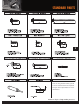
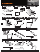
STANDARD PARTS 8 Note: If using treated lumber, special corrosive resistant screws are required. Ask your sales representative for more information. Details are subject to change without prior notice.
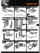
STANDARD PARTS 9
STANDARD PARTS 10
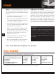
PRODUCT DESCRIPTION • 24" Coverage • 26 Gauge For color selections, please request a color chart. Galvalume Plus (20 Yr. WARRANTY) Limited Paint Warranties (UP TO 30 YEAR WARRANTIES) WARNING! AP Panel should not be installed on a roof that is less than a 3:12 pitch. When this panel is installed on pitches less than 3:12, heavy rainfall may lead to water accumulation and possible leaks.
STANDARD FASTENER LOCATIONS AT PANEL WARNING! Mueller trim comes with a protective film coating to aid in the prevention of scuffing. Do not allow this film to be exposed to the sun. Exposure will bond the film to the metal making removal difficult. NOTE: To comply with Texas Windstorm Certification Testing, #12x11 SDT Type A screws must be used in place of the #9 Woodgrip screws. 12 Details are subject to change without prior notice.
A-PANEL RECOMMENDED SCREW PLACEMENT TABLE With < 30’-0” mean roof height - 3:12 to 6:12 pitch for 90-140 mph wind speeds based on ASCE 7-93 FASTENING SCHEDULE SPACING ALONG PANEL NAIL STRIP WIND SPEED ZONE 110 120 90 100 Zone FASTENER SUBSTRATE ON CENTER SPACING ON CENTER SPACING ON CENTER SPACING Zone 1 #12-11 X 1” 15/32” CDX Type 1, 36” Type 1, 36” 19/32” CDX Type 1, 36” 7/16” OSB Zone 2 Zone 3 #12-11 X 1” #12-11 X 1” 130 140 ON CENTER SPACING ON CENTER SPACING ON CENTER SPACING
IMPORTANT INFORMATION OIL CANNING What is Oil Canning? Oil canning is a waviness that may occur in flat areas of light gauge, formed metal products. Structural integrity is normally not affected by this inherent characteristic and therefore is only an aesthetic issue. Things to Expect • Heat will increase oil canning, so high temperatures are often a factor when waviness occurs. • Changes in light — including overcast days, shade, and intense sunlight — can affect the appearance of oil canning.
DETAIL LOCATOR 9 5 7 2 4 3 1 6 8 15 DETAIL SECTION Details are subject to change without prior notice. Page 1 Eave . . . . . . . . . . . . . . . . . . . . . .15 2 Gable . . . . . . . . . . . . . . . . . . . . .17 3 Valley . . . . . . . . . . . . . . . . . . . . .20 4 Ridge . . . . . . . . . . . . . . . . . . . . .21 5 Hip . . . . . . . . . . . . . . . . . . . . . . .21 6 Endwall to Roof Transition . . . .22 7 Sidewall Flashing . . . . . . . . . . . .23 8 Pitch Change . . . . . . .
BEGINNING THE PROJECT STANDARD EAVE TRIM INSTALLATION 1. Install the eave trim by sliding it underneath the underlayment and securing it to the roof surface with wafer head screws on 5’ centers. 2. There are no screws or nails to be placed in the exposed fascia of the trim. 3. At the corners, cut the eave trim 1 1/2” long and prepare the ends with tabs to receive the gable trim. NOTE: Alternate trim profiles are acceptable using the screw pattern shown.
STANDARD EAVE TRIM INSTALLATION WITH GUTTER 1. Install the eave trim to the substrate with wafer head fasteners at 5’ O.C. 2. Position the roof panel so that the down slope end matches the dimension called for on the erection drawings. 3. Attach the roof panel with #9 x 1” woodgrip screw. (Refer to screw placement table). 4. Attach the roof panels at the eave with (6) #9 x 1” woodgrip screws - (4) per panel. 5. Attach the gutter with #14 x 7/8” lapteks @ 24” O.C. 6.
STANDARD ADJUSTABLE GABLE & STRIP INSTALLATION 1. Starting at the corner, install the adjustable gable trim along the sloping gable, placing it on top of the underlayment. 2. Attach with wafer head screws 5’ on centers (adjustable strip applied after valley trim). 3. Slide gable trim over eave trim at corner. 4. At the peak, one gable trim should be cut vertical to the ground and overlap at the junction of the two gable trims. NOTE: Alternate trim profiles are acceptable using the screw pattern shown.
STARTING AND ENDING PANEL INSTALLATION Starting Panel 1. Apply adjustable strip as previously instructed. 2. Remove the overlap rib of the panel, making a straight cut the length of the panel. 3. Apply butyl tape continuously down the length of the adjustable strip, covering the wafer head screw. 4. Insert the cut edge of the panel into the strip, making sure the panel is seated fully into the strip. 5. Attach the panel to the roof with #9 x 1” woodgrip screws on the required centers.
HIGH SIDE RESIDENTIAL EAVE TRIM INSTALLATION 1. Attach the high side trim (#0803) to the fascia with woodgrip screws on 5’ centers. Make sure the 6” side of the trim is on the rooftop with the receiver hem resting on the highs. 2. Cap the ends of the trim by cutting and folding a tab that attaches to the gable trim. The hem must be removed before a fold is made. Capping is usually easier to do before the trim is installed.
VALLEY PANEL AND TRIM INSTALLATION 1. Start at the low end, trim and place the valley flashing. The valley end should overhang the eave trim 1”. 2. If there is an end lap required in the valley pieces, caulk and lap at least 8”. 3. Use wafer head screws on 5’ centers to secure the valley in place along the outside edge. 4. Hem the edges of the valley over the eave trim, after trimming the center “V” back 1” to align with the edge of the eave.
STANDARD RIDGE ROLL and HIP INSTALLATION 1. Lay a piece of the #0221 ridge roll or hip in position, making sure it is centered and in the correct position. (Refer to step #8 for end capping instructions) 2. Temporarily fasten the ridge roll in place at one end with a woodgrip screw, positioning the screw through the hem of the ridge roll, centered between the ribs. 3. Field cut enough metal closures (#0322) to complete the application. 4.
ENDWALL TO ROOF FLASHING INSTALLATION 1. Insert the endwall flashing (#0725) behind the existing wall counter-flashing and attach to the wall using appropriate fasteners. Make sure the receiver hem of the endwall flashing is resting on the top of the roof sheet rib. If required, cap the ends of the trim by cutting and folding a tab. Remove the hems before making the folds. 2. If there is no counter-flashing, install counter-flashing using appropriate fasteners. 3.
SIDEWALL FLASHING INSTALLATION 1. Apply butyl tape to the bottom side of the J-closure. 2. Install the J-closure flush with the outer edge of the sidewall flashing and parallel to the ribs. 3. Secure with woodgrip screws on 12” centers. 4. Apply butyl tape continuously to top of J-closure. 5. Insert the sidewall flashing behind existing counter-flashing and secure to the J-closure with lap screws. 6. If there is no existing counter-flashing, install counter-flashing to wall with appropriate fasteners.
ROOF PITCH CHANGE INSTALLATION 1. Apply lower panels. 2. Install the transition flashing (#1487) making sure the bottom portion of the flashing is at the same pitch as the lower panels. Attach to decking 1” from top of flashing with wafer head screws on 5’ centers. 3. Field cut enough metal closures (#0322) to complete application. 4. Slide the 5/8” lip of the field cut metal closure into the receiver hem of the transition flashing and position the closure on the roof. 5.
STANDARD PANEL ENDLAP 1. Ensure the lower panel is installed completely (except for the top fasteners). 2. Install the butyl tape 10” from the top of the lower panel. Do not remove the paper backing from the butyl tape until upper roof panel lap and the top dimension have been confirmed. 3. Remove paper backing from the butyl tape. 4. Position and place upper panel so that a 12” lap is achieved. 5.
CHIMNEY INSTALLATION CHIMNEY FLASHING - UPHILL AND DOWNHILL UPHILL The uphill flashing will be 4” wider than the width of the curb (2” on each side). Cut an 1/8” slot in the two uphill corners of the panel slightly wider than 2 1/16”, so the 27 uphill flashing can slide through the two slots. UPHILL DOWNHILL 1. Trim both ends of the uphill and downhill sides of the flashing as indicated. 2. Slide the uphill flashing into the slots of the roofing and apply liberal amount of tube caulk.
CHIMNEY INSTALLATION CHIMNEY FLASHING - SIDE 1. Trim and bend the right side flashing as indicated. 2. Trim the left side in a similar fashion. NOTE: Alternate trim profiles are acceptable using the screw pattern shown. NOTE: The left and right side flashing are mirror images of each other. SIDE SIDE SIDE 28 FLASHING - VENT Procedures: 1. Trim the opening in the flashing to 20% smaller than the pipe diameter. 2. Slide the flashing down over the pipe. 3.
FIND OUT MORE ABOUT MUELLER, INC. Call 877-2-MUELLER (877-268-3553) This toll-free number connects you to one of our sales locations across the Southwest. Click www.MuellerInc.com Our interactive website offers photos and all the details of our metal products. Come by More than 30 locations. Our branches are staffed with experts who are always happy to answer any questions you may have.