CORRUGATED MANUAL METAL ROOFING INSTALLATION GUIDE
TABLE OF CONTENTS Preparation Requirements and Recommendations . . . . . . . . . . . . . . . . . . . . . . . . . . . . 3 Safety and Storage Considerations . . . . . . . . . . . . . . . . . . . . . . . . . . . . . . . . . . . . . . . . . 4 Care and Handling of Mueller Sheet Metal . . . . . . . . . . . . . . . . . . . . . . . . . . . . . . . . . . 5 Standard Parts . . . . . . . . . . . . . . . . . . . . . . . . . . . . . . . . . . . . . . . . . . . . . . . . . . . . . . . . . . . . 6 Product Description . . .
PREPARATION REQUIREMENTS & RECOMMENDATIONS This detail and installation manual has been provided to serve as a basic guideline for installing the Mueller corrugated panel roof system. This manual should be used in conjunction with the erection drawings to help ensure proper installation of this roof system. In case of discrepancies, the erection drawings will govern over this installation guide.
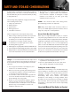
SAFETY AND STORAGE CONSIDERATIONS As with all major construction projects, safety should be a primary concern. The erector or contractor should be sure 5. All electrical tools should be inspected regularly for damaged cases or frayed electric cords. Extension that all OSHA safety rules are followed and that job safety cords should be inspected for damaged or frayed is strictly adhered to. insulation. Tools which do not meet good safety standards should not be used.
CARE AND HANDLING OF MUELLER SHEET METAL Delivery: Mueller takes every precaution to ensure that material is delivered to the customer damage-free and fully protected from the elements during shipment. When the material is delivered to the customer it then becomes the customer’s responsibility to protect the material from the elements, possible theft, and other damage.
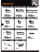
STANDARD PARTS 6 Details are subject to change without prior notice.
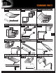
STANDARD PARTS 7 Details are subject to change without prior notice.
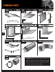
STANDARD PARTS 8 WARNING! Mueller trim comes with a protective film coating to aid in the prevention of scuffing. Do not allow this film to be exposed to the sun. Exposure will bond the film to the metal making removal difficult.
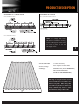
PRODUCT DESCRIPTION ATTACHMENT TO 1 x 4 WOOD PURLIN ATTACHMENT TO PLYWOOD TYPE 1: FASTENER LOCATION TYPE 1: CORRUGATED FASTENER LOCATION TYPE 2: FASTENER LOCATION NOTE: To comply with Texas Windstorm Certification Testing, #12x11 SDT Type A screws must be used in place of the #9 Woodgrip screws. 9 • 34" Overall width • 29.5" Coverage • 26 Gauge For color selections, please request a color chart. Galvalume Plus (20 Yr.
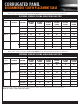
CORRUGATED TABLE OF CONTENTSPANEL RECOMMENDED SCREW PLACEMENT TABLE With < 30’-0” mean roof height - 3:12 to 6:12 pitch for 90-140 mph wind speeds based on ASCE 7-93 FASTENING SCHEDULE SPACING ALONG PANEL NAIL STRIP 90 100 WIND SPEED ZONE 110 120 130 140 Zone FASTENER SUBSTRATE ON CENTER SPACING ON CENTER SPACING ON CENTER SPACING ON CENTER SPACING ON CENTER SPACING ON CENTER SPACING Zone 1 #12-11 X 1” 15/32” CDX 42” 42” 42” 42” 42” 42” 7/16” OSB 30” 30” 30” N/A N/A N/A 1x4 W
DETAIL LOCATOR 11 DETAIL SECTION Page 1 Eave . . . . . . . . . . . . . . . . . . . . . . 12 2 Gable . . . . . . . . . . . . . . . . . . . . . 14 3 Valley . . . . . . . . . . . . . . . . . . . . . 16 4 Ridge 5 Hip . . . . . . . . . . . . . . . . . . . . . . . 17 6 Endwall to Roof Transition . . . . 18 7 Sidewall Flashing . . . . . . . . . . . . 19 8 Pitch Change . . . . . . . . . . . . . . 20 9 Chimney Flashing . . . . . . . . . 22-23 . . . . . . . . . . . . . . . . . . . .
BEGINNING THE PROJECT STANDARD EAVE TRIM INSTALLATION 1. Install the eave trim by sliding it underneath the underlayment and securing it to the roof surface with wafer head screws on 5’ centers. 2. There are no screws or nails to be placed in the exposed fascia of the trim. 3. At the corners, cut the eave trim 1 1/2” long and prepare the ends with tabs to receive the gable trim. NOTE: Alternate trim profiles are acceptable using the screw pattern shown.
STANDARD EAVE TRIM INSTALLATION WITH GUTTER 1. Install the eave trim to the substrate with wafer head fasteners at 5’ O.C. 2. Position the roof panel so that the down slope end matches the dimension called for on the erection drawings. 3. Attach the roof panel with #10 x 1” woodgrip screw. (Refer to screw placement table). 4. Attach the roof panels at the eave with #10 x 1” woodgrip screws - Reference Type 1 Fasteners. 5. Attach the gutter with #14 x 7/8” lapteks @ 12” O.C. 6.
STANDARD ADJUSTABLE GABLE & STRIP INSTALLATION 1. Starting at the corner, install the adjustable gable trim along the sloping gable, placing it on top of the underlayment. 2. Attach with wafer head screws 5’ on centers (adjustable strip applied after valley trim). 3. Slide gable trim over eave trim at corner. 4. At the peak, one gable trim should be cut vertical to the ground and overlap at the junction of the two gable trims. NOTE: Alternate trim profiles are acceptable using the screw pattern shown.
HIGH SIDE RESIDENTIAL EAVE TRIM INSTALLATION 1. Attach the high side trim (#0802) to the fascia with woodgrip screws on 5’ centers. Make sure the 6” side of the trim is on the rooftop with the hem resting on the highs. 2. Cap the ends of the trim by cutting and folding a tab that attaches to the gable trim. Capping is usually easier to do before the trim is installed. If done after the trim is installed, be sure and leave 6” of the trim overhanging to allow enough material for cut and folds. 3.
VALLEY PANEL AND TRIM INSTALLATION 1. Start at the low end, trim and place the valley flashing. The valley end should overhang the eave trim 1”. 2. If there is an end lap required in the valley pieces, caulk and lap at least 8”. 3. Use wafer head screws on 5’ centers to secure the valley in place along the outside edge. 4. Hem the edges of the valley over the eave trim, after trimming the center “V” back 1” to align with the edge of the eave.
STANDARD RIDGE ROLL and HIP INSTALLATION 1. Lay a piece of the #0221 ridge roll or hip in position, making sure it is centered and in the correct position. (Refer to step #7 for end capping instructions) 2. Temporarily fasten the ridge roll in place at one end with a lap screw, positioning the screw through the hem of the ridge roll, centered on the corrugation. 3. Position the corrugated closure on the sheet. 4. Attach with (1) lap screw, centered on the corrugation, 12” O.C.
ENDWALL TO ROOF FLASHING INSTALLATION 1. Insert the endwall flashing (#0724) behind the existing wall counter-flashing and attach to the wall using appropriate fasteners. Make sure the receiver hem of the endwall flashing is resting on the top of the roof sheet rib. If required, cap the ends of the trim by cutting and folding a tab. 2. If there is no counter-flashing, install counter-flashing using appropriate fasteners. 3. Position the corrugated closure on the roof. 4.
SIDEWALL FLASHING INSTALLATION 1. Apply butyl tape continuously to top of corrugation. 2. Insert the sidewall flashing behind existing counter-flashing and secure to the top of corrugation with lap screws. 3. If there is no existing counter-flashing, install counter-flashing to wall with appropriate fasteners. NOTE: Alternate trim profiles are acceptable using the screw pattern shown. 19 Details are subject to change without prior notice.
ROOF PITCH CHANGE INSTALLATION 1. Apply lower panels. 2. Install the transition flashing (#1486) making sure the bottom portion of the flashing is at the same pitch as the lower panels. Attach to decking 1” from top of flashing with wafer head screws on 5’ centers. 3. Position the corrugated closure on the roof. 4. Attach using one lap screw, centered on corrugation, 12” O.C., through the hem of the transition flashing and corrugated closure, into the panel.
STANDARD PANEL ENDLAP 1. Ensure the lower panel is installed completely (except for the top fasteners). 2. Install the butyl tape 10” from the top of the lower panel. Do not remove the paper backing from the butyl tape until upper roof panel lap and the top dimension have been confirmed. 3. Remove paper backing from the butyl tape. 4. Position and place upper panel so that a 12” lap is achieved. 5.
CHIMNEY INSTALLATION CHIMNEY FLASHING - UPHILL AND DOWNHILL UPHILL 22 The uphill flashing will be 4” wider than the width of the curb (2” on each side). Cut an 1/8” slot in the two uphill corners of the panel slightly wider than 2 1/16”, so the uphill flashing can slide through the two slots. UPHILL DOWNHILL 1. Trim both ends of the uphill and downhill sides of the flashing as indicated. 2. Slide the uphill flashing into the slots of the roofing and apply liberal amount of tube caulk.
CHIMNEY INSTALLATION CHIMNEY FLASHING - SIDE 1. Trim and bend the right side flashing as indicated. 2. Trim the left side in a similar fashion. NOTE: Alternate trim profiles are acceptable using the screw pattern shown. NOTE: The left and right side flashing are mirror images of each other. SIDE SIDE SIDE 23 FLASHING - VENT Procedures: 1. Trim the opening in the flashing to 20% smaller than the pipe diameter. 2. Slide the flashing down over the pipe. 3.
FIND OUT MORE ABOUT MUELLER, INC. Call 877-2-MUELLER (877-268-3553) This toll-free number connects you to one of our sales locations across the Southwest. Click www.MuellerInc.com Our interactive website offers photos and all the details of our metal products. Come by More than 30 locations. Our branches are staffed with experts who are always happy to answer any questions you may have. Find us On Facebook, check out our latest news and events.