Prefabricated Steel Building Installation Manual
Table of contents A. Site and Foundation Preparation General Information . . . . . . . . . . . . . . . . . . . . . . . . . . . . . . . . . . . . . . . . . . . . . . . . . 1 Squaring of Foundation . . . . . . . . . . . . . . . . . . . . . . . . . . . . . . . . . . . . . . . . . . . . . . 2 Anchor Bolt Settings . . . . . . . . . . . . . . . . . . . . . . . . . . . . . . . . . . . .
METAL BUILDING TERMS AND DEFINITIONS F. Trim Flashing . . . . . . . . . . . . . . . . . . . . . . . . . . . . . . . . . . . . . . . . . . . . . . . . . . . . . . . . . . 1 Peak Sheet Ridge Installation . . . . . . . . . . . . . . . . . . . . . . . . . . . . . . . . . . . . . . . . . . 2 Typical Screw Placement for Peak Sheets/Ridge Roll . . . . . . . . . . . . . . . . . . . . . . . .
Section Site & Foundation Preparation A
PREPARATION OF SITE AND FOUNDATION 1. General Before the Mueller prefabricated steel building arrives, the site and foundation should be prepared. This includes leveling the terrain and constructing the foundation. Mueller buildings are typically designed to be placed on a permanent slab. A concrete contractor is highly recommended for this phase of the construction. 2. Procedural Steps A. Remove trees, debris, and other items from the building location. B.
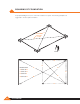
SQUARING OF FOUNDATION For proper building erection, it is critical the foundation is square. The following examples are suggested to ensure square foundation.
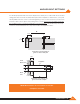
ANCHOR BOLT SETTINGS It is extremely important that anchor bolts be placed accurately in accordance with the anchor bolt setting plan. All anchor bolts should be held in place with a template or similar means, so they will remain plumb and in the correct location during placing of the concrete. Check the concrete forms and anchor bolt locations prior to the pouring of the concrete. A final check should be made after the completion of the concrete work and prior to the steel erection.
ANCHOR BOLT SETTINGS Refer to your anchor bolt drawing for proper sizes and dimensions. Stake Template Form Board Anchor Bolts Anchor Bolt 11/2˝ 11/2˝ Foundation Sheet Ledge Note: Suggested protrusion is 2 1/2" of threads above concrete.
Section Building Delivery And Storage B
UNLOADING AND PREPARATION OF PARTS FOR ASSEMBLY The vehicle transporting your building parts must gain access to the building site from the adjacent highway or road. Such access should be studied and prepared in advance of arrival. All obstructions, overhead and otherwise, must be removed and the access route graveled or planked if the soil will not sustain the heavy wheel loads. A forklift or other type of power loader may be required to unload the truck and move the heavier parts to the proper locations.
UNLOADING, HANDLING, AND STORAGE OF MATERIALS Structure A great amount of time and trouble can be saved if the building parts are unloaded at the building site according to a pre-arranged plan. Proper location and handling of components will eliminate unnecessary handling. Blocking under the columns and rafters protects the splice plates and the slab from damage during the unloading process.
LOCATION OF BUILDING PARTS Place the parts around the foundation so they will be in the most convenient locations for installation. For example: place the end columns and rafters at the ends of the building and the mainframe columns and rafters at the sides. Place the bolts and nuts in a place where they will be accessible to the parts. You may want to screw the bolts and nuts together and place them with the corresponding parts. This will save time as you begin assembling the parts.
CARE AND HANDLING OF MUELLER SHEET METAL Delivery Mueller takes every precaution to ensure that material is delivered to the customer damage free and fully protected from the elements during shipment. When the material is delivered to the customer it then becomes the customer's responsibility to protect the material from the elements, possible theft, and other damage.
WALL AND ROOF PANELS Mueller’s wall and roof panels including color coated, galvalume, and galvanized provide excellent service under widely varied conditions. All unloading and erection personnel should fully understand that these panels are quality merchandise which merit cautious care in handling. Under no circumstances should panels be handled roughly. Packages of sheets should be lifted off the truck with extreme care taken to ensure that no damage occurs to ends of the sheets or to side ribs.
WALL AND ROOF PANELS (continued) Storage: It is recommended that sheets be stored under roof if at all possible. If sheets are to be stored outside, the following precautions should be observed: 1. The storage area should be reasonably level, and located so as to minimize handling. 2. When stored on bare ground, place a plastic ground cover under the bundles to minimize condensation on the sheets from ground moisture. 3.
Section Erection of Primary And Secondary Structural C
GENERAL INFORMATION Many methods and procedures are in use for erecting the structural portion of metal buildings. The techniques of raising frames vary from erecting small clear spans and endwall frames in units to erecting the larger clear spans and modular frames in sections. The erection methods used depend strictly on the type of building, the available equipment, the experience level of the crews, and the individual job conditions.
TOOLS AND EQUIPMENT REQUIRED The types of tools and equipment required in order to assemble and erect the building depend on the size of the building purchased. This part of the instruction manual lists the tools and equipment that are normally required for most buildings. You may wish to use more or less power equipment or different tools than are listed as the need dictates.
End wall door column (EWDC) Door header (DH) End wall interior column (EWIC) Beam end wall column (EWC) End wall girt (EWG) Base angle (BA) End wall extension Wide flange beam frame (MFR) Long lap Z-bar (LLZ) Eave strut / Eave purlin (ES) Z-bar wall girt (WG) Extension Cable bracing (BC) Rigid frame extension Rigid frame with straight column (MFR) Rigid frame extension with straight column Rigid frame with tapered column (MFR) Rigid frame with straight column & pipe interior column Typical b
RAISING RIGID FRAMES The intermediate or interior frames nearest the bearing endwall are usually erected first. This bay usually contains the diagonal bracing. The proper completion and plumbing of this first bay is extremely important to the successful completion of the building.
RAISING RIGID FRAMES (CONTINUED) After the columns have been erected, the ground-assembled rafter is hoisted into place and connected to the columns. The size of the rafter that can be safely handled depends on the equipment available and the experience of the erection foreman. Generally as many connections as possible are made on the ground. Flange braces loose bolted The flange brace should be bolted to the rafter prior to raising in order to save time.
RAISING RIGID FRAMES (CONTINUED) Lifting Cables And Spreader Bars In all instances the length of the lifting cables should be such that the angle between the rafter and the lifting cables is no less than 45 degrees. To reduce the severe compression stresses at the ridge of the rafters that are created by the angle of lifting cables, a spreader bar is recommended, which allows the lifting cables to be parallel to each other.
RAISING RIGID FRAMES (CONTINUED) Completing And Plumbing The First Bay After the first intermediate or interior frames have been set, Mueller, Inc. recommends that all purlins, girts, and eave struts be installed in the braced bay and the entire bay plumbed, aligned and braced before proceeding further. If the building is designed without cable bracing, the erector is responsible for providing temporary erection bracing.
RAISING RIGID FRAMES (CONTINUED) When the rafters consist of several roof beams, as in the case of wide buildings, a safe procedure of raising by sections and supporting the free end must be followed, regardless of the type of equipment available. In most instances the work proceeds from outside columns inward toward the peak until the entire frame is bolted into place. The same general procedures of erection apply to either clear span or multiple span frames.
ERECTING COLUMN AND BEAM ENDWALLS Column and beam endwalls of 50 feet or less in span may be raised into position and set on the anchor bolts as a unit. All rafters, column, girts (except outside endwall girts which connect to the sidewall girts), door headers, door jambs, clips, diagonal brace rods, etc. should be assembled on the ground with the bolts left finger tight. A spreader bar should be used to raise the endwall frame.
ERECTING THE REMAINING FRAMES & Eave struts The remaining frames are erected in like manner, initially with only a few purlins being installed in each bay working from one end of the building to the other. To lend overall rigidity to the structure, install flange braces to the purlins at specified locations. All purlin, girt and eave strut connection bolts are left loose so the entire skeleton framework can be plumbed without undue difficulty.
JOINTS NOT SUBJECT TO TENSION LOADS Joints not subject to tension loads need only be tightened to the snug tight condition, defined as the tightness attained by a few impacts of an impact wrench or the full effort of a man using an ordinary spud wrench. Joints Subject To Tension Loads Two tightening procedures are specified for A325 bolts in joints subject to tension loads, turn-ofthe-nut method and direct tension indicator.
ASSEMBLY OF BRACE CABLES 1. Assembly of brace cables: Note: Cable may have to be field cut to proper length. A. Insert grip through eyebolt. B. Begin wrapping the grip around the cable, matching the crossover marks. C. Continue until the lasts two wraps are left split the legs and apply separately. D. Duplicate this procedure on each end.
INSTALLATION OF WIND BRACING (CONTINUED) Assemble the next brace cable the same way and connect to the next column to form an “X” with the other cable. Column Cable Turnbuckle Eyebolt To square the building, measure the length of the diagonals and tighten or loosen the turnbuckle/ eye-bolt until the lengths are the same. Double-check by using a square at the corners. Brace each sidewall frame the same way so that you have an x-brace on each side.
INSTALLATION OF THE WIND BRACING Diagonal bracing in metal buildings is critical. They provide support for wind loads or other longitudinal loads, such as those created by an overhead crane in the completed structure. Many times additional temporary bracing is needed to stabilize the structure during erection. The erector should review this requirement, and the erector should provide any additional bracing.
INSTALLATION OF WIND BRACING (CONTINUED) Hillside Washer Installation Hex Nut Flat Washer Hillside Washer Note: Hillside washer installation similar at base. Note: Care should be taken not to over-tighten the wind bracing. Overtightening the bracing can cause premanent damage to the framing. www.muellerinc.
INSTALLATION OF WIND BRACING (CONTINUED) Occasionally the bracing in the wall of a building cannot be installed in the specified bay because of doors or other complications. Usually these can be moved to other bays without affecting the structural integrity of the building. However, before moving any wind bracing check with Mueller, Inc. Do not remove after building is erected.
Section Insulation D
WALL INSULATION Fiberglass blanket insulation is the most common type used, and these instructions pertain to this type only. One side of the blanket insulation should have a vapor barrier that must face the inside of the building regardless of whether the insulation is for heating or cooling. Fiberglass insulation to outside of building Vapor barrier to inside of building Wall Insulation Installation Cut the insulation to length allowing an additional 6” or more to facilitate handling.
WALL INSULATION (CONTINUED) The first run of wall insulation should be installed so that its forward edge is just ahead of the leading edge of the wall panel. This keeps the forward edge of the insulation ahead of the wall panel for joining the next blanket.
ROOF INSULATION Pre-cut roof insulation to reach from eave to eave allowing approximately 2 feet of additional length to facilitate handling. Hold insulation at one sidewall and roll out insulation across the purlins, vapor barrier to the inside of the building. Stretch the insulation to provide a tight and smooth inside surface. Note: Insulation has no load bearing strength. Maintain body weight on approved scaffold or walk boards. www.muellerinc.
ROOF INSULATION (CONTINUED) Double sided tape or contact adhesives can be used to hold insulation in place while the roof sheets are being installed. Trim excess insulation to the edge of the eave trim and cut fiberglass approximately 4 inches from end leaving only facing. Fold facing over end of blanket insulation to seal the end.
ROOF INSULATION (CONTINUED) Seal insulation sidelap joints by lapping 4” tab side. As on the walls, the general sequence is to install the roof sheets in conjunction with the insulation. First Roof Panel 4'-0" 1'-0" Blanket Insulation Double-sided Tape Eave Trim Eave Strut Note: The insulation sidelap must be lapped to prevent condensation and minimize temperature loss at laps. Warning! Wipe oil and other slippery substances from roof panels.
Section Sheeting E
FASTENER LAYOUT Lap Tek Screw 20" O.C. at sidelap #12 Self Drill Roof Fastener Sealant Tape “R” and “PBR” Roof Panel Fastener Spacing, Intermediate Purlins, Girts, Eave Strut Lap Tek Screw 20" O.C.
ALIGNING THE GIRTS Installation of the building walls is generally done before the roof. Before starting the wall installation, check to be sure that the eave strut and girts are straight and plumb. One method of aligning the girts is to cut temporary wood blocking to the proper length and install between the lines of girts. This blocking can be moved from bay to bay, which will reduce the number of pieces required. Normally, one line of blocking per bay will be sufficient.
SCREW ALIGNMENT Good alignment of the screws, especially on the wall panels, will give a professional appearance to the wall panel installation. One way this can be accomplished is by pre-drilling holes in the panels at identical locations. Up to 15 panels can be stacked together and drilled using a template panel. Use 1/8” or 5/32” diameter drill bit for panel to structural fasteners and a 1/4” diameter bit for the sidelap clearance holes.
SCREW ALIGNMENT (CONTINUED) The template panel should be laid out for the proper screw locations in accordance with the building erection drawings. Since pre-drilling will “hand” the panels, it will also be necessary to select the end of the building from which the paneling is to begin. Before drilling the template panel, it should be checked for proper hole locations against the building framework. Be sure there is no excessive deflection in the purlins and girts.
INSTALLATION OF WALL PANELS Adjoining panels are installed with the overlapping rib toward the last erected panel. Position panel to structural making sure that it is kept plumb and install fasteners at lapped rib. Check for proper coverage (3' center to center) and correct as necessary. Install remaining fasteners. ng eti ion e Sh rect Di Blanket Insulation Wood Blocking Steel Frame Line Wall Panel Wall Panel Note: Start first panel with major rib centered with endwall frame. www.muellerinc.
INSTALLATION OF WALL PANELS (CONTINUED) Backlapping the wall panels 1 foot or 2 foot is routinely done to match panel coverage with the building width and length. On the sidewall this is done with the last panel installed. On the endwall this is normally done near the center and will be marked on the erection drawings.
STANDARD SHEET LEDGE Base Angle Wall Sheet (R-Panel Shown) Base Flashing (Optional) 11/2" Sheet Ledge 1/8" Spacing under sheet 1/8" to 1/4" for edge creep Note: Sheets must be at least two inches off the ground, or rust may occur. OPTIONAL SHEET LEDGE WITH EXISTING SLAB Wall Sheet (R-Panel Shown) Base Angle Base Flashing Note: Sheets must be at least two inches off the ground, or rust may occur. www.muellerinc.
FASTENER INSTALLATION Correct fastener installation is one of the most critical steps when installing roof panels. Drive the fastener in until it is tight and the washer is firmly seated. Do not overdrive fasteners: A slight extrusion of neoprene around the washer is a good visual tightness check. Always use the proper tool to install fasteners. A fastener driver (screw gun) with and RPM of 1700-2500 should be used for self-drilling screws.
SAFETY NOTE! CAUTION!!! PANELS MAY BE SLICK UNSECURED PANELS MAY SLIP IF STEPPED ON! Never step on a single unsecured roof panel, or a stack of roof panels laying unattached on the purlins. Secure each end of the panel with clamps or appropriate fasteners and place walk boards of adequate size and strength in the flat of any panels not fully secured to the purlins and supported by panels on each side.
PREPARING THE EAVE After installing the first run of insulation, prepare the eave for the first roof panel by applying sealant tape along the eave outside of the insulation and leaving release paper in place. Sealant must be applied in a straight line and without voids. Do not stretch the sealant. Use a knife to cut if necessary. Cut an inside closure strip as shown and place starter piece on top of the sealant (removing protective paper from the sealant only as required).
PREPARING THE EAVE (CONTINUED) Along the top of the closures that have been placed along the eave, apply a second run of sealant tape. Prior to removing paper backing, check and mark for proper alignment of the first roof panel. Continue sealant tape and closure run along eave in preparation for the next roof panel.
INSTALLATION OF FIRST ROOF PANEL Once the eave is prepared, the first roof panel may be installed. Check the erection drawings to determine the roof overhang at the eave. Set the roof panel in place over the inside closure (after removing the paper from the sealant tape) ensuring the major ribs of the panel nest properly with the inside closure. Align the center of the major rib of the panel edge with the edge of the endwall roofline.
INSTALLATION OF ROOF PANELS With the first panel run installed and secured, and sidelap sealant applied, the second panel run may be started. Prepare the eave with an inside closure and sealant tape as shown previously. Position the panel so the overlapping ribs will nest properly. Be sure to check for proper overhang and panel coverage. Lap screw the major ribs of the two panels together, and fasten panel to the purlins.
“R” PANEL High Side Attachment (6 Fasteners Per Panel) pe Slo R Panel Sidelap Attachment (See Detail B) Endlap Attachment (See Detail A) Eave Attachment (6 Fasteners Per Panel) Intermediate Purlin Attachment (3 Fasteners Per Panel) 12" R Panel Self Drill (6 each per panel) Sealant Tape Lap Tek Screw (20" O.C.) Sealant Tape Sealant Tape Detail A Detail B Sidelap 1. Sealant tape must be installed between weather infiltration point and fastener. 2. Install Lap Tek fasteners at 20” on center. 3.
ROOF SHEETING SEQUENCE It is recommended that both sides of the ridge of a building be sheeted simultaneously. This will keep the insulation covered for the maximum amount of time and the panel ribs can be kept in proper alignment for the ridge panel. Check for proper coverage as the sheeting progresses. Note panel-sheeting sequence below. 11 10 12 7 8 4 2 9 5 6 3 1 Note: If slippery substances are present on the roof panels wipe them clean immediately to prevent slipping or falling.
SECTION AT EAVE Roof Fastener Panel Sealant Tape Closure Sealant Tape Insulation Double-sided Tape Eave Trim (Trim shape may vary) Wall Fastener Lap Screw Eave Strut Wall Panel Note: Check erection drawings for appropriate overhang dimensions.
SEALING THE SIDELAP Apply the sidelap sealant tape to the weather side edge of the lower panel’s major rib as shown. The sealant tape should only be applied to clean, dry surfaces. With the release paper in place, press firmly along the length of the sealant to ensure proper adhesion. In removing the protective paper from the sealant tape, care should be taken not to pull the sealant tape away from the panel. Install the adjoining panel positioning the overlapping rib with care.
SEALING THE EAVE Sealant tape location at the eave is critical. To ensure a weather tight seal, the sidelap sealant must extend down from the top of the rib to the sealant on the eave closure. The sealant extension must splice into the eave sealant tape. Sealant Tape Panel Major Rib Sealant Tape (Above & Below Closure) Fastener Sealant Extension Inside Closure Strip with Adhesive Backing Note: Workers should maintain a constant awareness of their location in relation to the roof edge at all times.
SEALING THE ENDLAPS At the panel endlaps place a run of sealant tape across the full panel width ½" below the fastener line. The panel endlaps have a 12" minimum overlap located over a purlin as shown. Locate the fasteners 1” above the purlin web according to the fastener layout. 12" Lap Ridge Roof Fastener Roof Panel Purlin Web Sealant Tape Sealant Tape Eave Purlin Note: Do not step on panel endlaps until fully secure with fasteners. www.muellerinc.
PANEL ENDLAPS Apply sealant tape to far side of major rib to complete seal at panel lap.
INSTALLATION OF FINAL PANEL While backlapping the last roof panel (to match panel coverage with the building length) is routinely done, this installation method can compromise the integrity of the roof by trapping moisture between the panels. This moisture could, in time, create an environment conducive to rust and metal failure. Manufacturer recommends field cutting the final panel lengthwise to create the desired panel width necessary to finish off the building.
Rope Sealer Placement Panel Rib Lap Tek Screw (20" O.C.
DIE FORMED TRANSITION TRIM 12" 31/4" 1" 3/4" 11/2" 31/2" 3/8" 13/4" 10'-0" Transition Trim 6" Sealant Tape 11/2" 2" 21/2" Multiple Uses Roof Sheet Transition Trim Wall Roof Sheet Wall Sheet Transition Trim Roof Sheet Transition Trim Roof Sheet www.muellerinc.
SAFETY PRECAUTIONS FOR ROOFING WORK Manufacturer strongly recommends that erection employees be continuously trained in safe and productive work practices. Working on the roof area in the installation of roof structurals, insulation or roof panels requires proper training, correct equipment and constant alertness to minimize the danger of falls. Hard hats should be worn on job sites to prevent injury from falling objects.
UL 90 LIGHT TRANSMITTING PANEL INSTALLATION R-Panel Sealant Tape pe Slo R-Panel Sealant Tape pe Slo Install roof panels, leaving the light-transmitting panel run open, except for lower light transmitting panel run panel. Install sealant tape to panel sidelaps and across panel width as normal. Lay light transmitting panel in place overlapping lower metal panel 12”. Do not install any fasteners at this time. Install sealant tape down light transmitting panel side laps.
UL 90 LIGHT TRANSMITTING PANEL INSTALLATION (CONTINUED) R-Panel Sealant Tape pe Slo Lap 12" O.C. pe Slo Apply sealant tape across sidelaps of 3” long pieces of “R” panel. Be sure the light transmitting panel sidelaps have a complete run of sealant tape on top of the light-transmitting panel. Install “R” panel hat section to each side of light transmitting panel with lap screws at 12” O.C.
Section Trim F
FLASHING, GUTTER AND TRIM The correct installation of flashing, gutters, and trim cannot be overemphasized. The overall appearance of the finished building depends primarily on the quality of the installation of the flashing, gutters and trim. Keep all gutter and flashing lines straight. Make all bends sharp and neat. Be sure edges are not jagged, dented, crimped, or serrated. End joints and laps must be closely controlled.
PEAK SHEET RIDGE INSTALLATION Peak sheet ridge panels are to be installed as each side of the roof is sheeted. This will aid in keeping both sides of the roof aligned. After having installed a run of panels on each side of the roof, apply sealant to the panels as shown. Set die formed ridge panel in place and install lap and purlin fasteners. Apply sealant tape along the top of the leading rib to prepare for the next sidelap.
TYPICAL SCREW PLACEMENT ON PEAK SHEETS Lap Tek Screw Peak Sheet Roof Sheet (R-Panel Shown) Self Drill Screw TYPICAL SCREW PLACEMENT ON RIDGE ROLL Lap Tek Screw (1' Typical) Roof Sheet (R-Panel Shown) Ridge Roll Outside Closure www.muellerinc.
SEALANT TAPE APPLICATION AT RIDGE FLASHING Apply panel sidelap sealant tape as shown for building with ridge flashing and outside closures. The sealant tape is placed along the inside edge of the major rib from the ridge purlin web line to the upper end of the panel.
RAKE TRIM AND PEAK BOX INSTALLATION Rake trim and/or peak box should lap over rake trim a minimum of 2 inches. Attach to wall panel with lap tek screws. Peak box may be attached to rake trim with lap tek screws or rivets. Seal the connection at the roof panel with sealant tape or caulk. Rake Trim Roof Panel Peak Box Sealant Tape Wall Panel Note: Mueller recommends an outside closure under bottom edge of rake trim, to prevent birds from nesting in trim.
CORNER TRIM Outside Corner Detail R-Panel Outside Corner Trim Lap Tek 24" O.C. Wall Girt Inside Corner Detail (Used with liner panel condition only) Wall Girt R-Panel Inside Corner Trim Lap Tek 24" O.C. Note: Install corner trim with lap tek faseners 24" O.C.
STANDARD EAVE TRIM Tek Screw in Flat of Sheet Sealant Tape Inside Closure Sealant Tape Standard Eave Trim Roof Panel Tek Screw Lap Tek Screw Purlin or Eave Strut Wall Panel Standard Eave / Sculptured Rake Trim With Rake End Cap Rake Trim Standard Eave Trim Rake End Cap Corner Trim Note: Roof sheet should extend 2" to 3" past eave trim. www.muellerinc.
SCULPTURED EAVE TRIM Sealant Tape Tek Screw in Flat of Sheet Inside Closure Sealant Tape Roof Panel Tek Screw Purlin or Eave Strut Sculptured Eave Trim Lap Tek Screw Optional Closure Wall Panel F-8 877-2-MUELLER
SCULPTURED EAVE / RAKE TRIM WITH CORNER BOX Rake Trim Sculptured Eave Trim Pop Rivets or Lap Tek Screws Corner Box Note: Roof sheet should extend 2" to 3" past eave trim. www.muellerinc.
MUELLER GUTTER SYSTEM DIAGRAM Gutter Strap Roof Panel Gutter Purlin or Eave Strut Downspout Sleeve Pop Rivet or Lap Tek Screw Wall Panel Downspout Strap Wall Girt Downspout Pop Rivet or Lap Tek Screw Base Angle Downspout Kickout Base Trim F-10 877-2-MUELLER
GUTTER STRAP INSTALLATION Lap Tek Screw in Flat Area of Sheet Gutter Strap Roof Panel Gutter Purlin or Eave Strut Screw Placement Side View Metal Roofing Lap Tek Screws Gutter Strap Gutter Screw Placement Top View www.muellerinc.
DOWNSPOUT SLEEVE INSTALLATION Pop Rivets Inside Bottom of Gutter Gutter Downspout Sleeve Gutter Downspout Sleeve F-12 877-2-MUELLER
GUTTER WITH CORNER BOX Rake Trim Gutter Gutter Strap Pop Rivets or Lap Tek Screws Corner Box www.muellerinc.
DOOR TRIM INSTALLATION “J” trim pieces are provided to trim out edges around framed openings. “J” trim pieces should be attached to door columns and header before wall sheets are attached. After trim is attached, the trimmed wall sheets can be inserted behind the “J” trim then screwed down in place. Door Head Trim Door Jamb Trim Door Opening Note: Clean all metal shavings from wall sheets to ensure against damage to the coating.
TYPICAL DETAILS – HEAD/JAMB Jamb Wall Girt Door Jamb Jamb Trim R-Panel Self-Drill Screw 3' O.C. Head R or U-Panel Self-Drill Screw Purlin Self-Drill Screw Head Trim Door Head Note: Install jamb and head trim with self-drilling fasteners at 3' O.C. www.muellerinc.
OVERHANG TRIM DETAILS Endwall Overhang Purlin Roof Panel Rake Trim Angle Flashing Endwall Rafter Soffit Sheet Angle Flashing Wall Panel Endwall Overhang At Ridge Ridge Roll Flashing Sidewall Overhang With Eave Trim Roof Panel Soffit Sheet Sidewall Overhang With Gutter Roof Panel Roof Panel Wall Panel Purlin Purlin Gutter Eave Trim Angle Flashing F-16 877-2-MUELLER Soffit Sheet Angle Flashing Soffit Sheet Angle Flashing
Section Doors and Accessories G
PERSONNEL DOORS Personnel (walk-in) doors can be installed at any location in the building. Wall girts below the standard level of seven feet four inches will have to be cut out for the doorframe. After deciding where the door is to be located and before the wall sheets are installed, attach the doorframe to the foundation and the wall girt or girts. The doorframe can be bolted to the girt and foundation where and however desired. The base angle will have to be cut out in the door opening.
MeTal bUIlDInG DooR fRaMe Wall Sheet Cee Purlin Door Head Trim Wall Sheet Zee Purlin Door Head Trim Head section Head section corner connection Wall Sheet Purlin Intermediate Purlin connection standard frame Details no sub-frame Required sill anchor G-2 877-2-MUELLER
ROLL-UP DOORS Instructions for Assembly Included with Roll-up Doors. See Package. WINDOW INSTALLATION See manufacturer's instructions. www.muellerinc.
venT InsTallaTIon Roof ventilators (optional) 1 . Ventilators may be installed on the roof ridge after the roof sheets are on and before the ridge roll or peak sheet is installed . The ventilators are ten feet long and usually are installed at the peak and between two rafters . 2 . Cut out the ridge roll or peak sheet to fit the opening of the ventilator . Ensure that the opening is cut correctly so the ventilator will fit properly and provide enough lap over the opening to prevent leaks .
conTInUoUs RIDGe venTIlaToRs Birdscreen Peak Panel 10' Continuous Vent Roof Panel Outside Closure Strip w/ Sealant Tape End Cap Skirt Rain Shield Wind Band Interior Frame Outside Closure Strip w/ Sealant Tape Damper (Optional) Throat section Throat Ga. A B C 9" 26 22 12 ¾ 15 ¼ 12" 26 28 ¼ 17 ¼ 19 ½ www.muellerinc.
VENT SEALERS Closure Roof Panel Sealant Tape 61/2˝ Foam Closure End Skirt Peak Sheet Roof Pitch Less than 1:12 Install the end cap for 1:12 pitch roof slope and foam closure with tape sealant top and bottom.
venT InsTallaTIon Vent section b Roof Panel section a End Skirt, attach to leading vent Vent Blind Rivets (4 required) End Skirt Gutter Sealant Tape End Skirt Fasteners (2 required on each side of vent) Roof Panel Vent End Cap Blind Rivets (4 required) End Skirt End Skirt Gutter Outside closure with tape sealer top and bottom. (Field notch around end skirt gutter). End Skirt Fasteners Outside closure with tape sealer top and bottom. (Field notch around end skirt gutter).
PIPE DECK FLASHING INSTALLATION 1. Trim Cut opening to 20% smaller than pipe diameter. 2. Slide Slip pipe flash over pipe. 3. Seal Apply urethane/silicone sealant between pipe flash and roofing. 4. Form Bend aluminum base to fit irregularities. Use large slot screwdriver to press into tight angles. 5. Fasten Complete the seal using common weatherresistant fasteners.
Section Glossary: Metal Building Terms & Definitions H
METAL BUILDING TERMS AND DEFINITIONS Anchor Bolt Plan: A plan view showing the size, location and projection of all anchor bolts for the metal building system components, the length and width of the foundation (which may vary from the nominal metal building size). Column reactions (magnitude and direction) and minimum base plate dimensions may also be included.
METAL BUILDING TERMS AND DEFINITIONS Brace Rods: Rods or cables used in roof and walls to transfer loads such as wind loads, and seismic and crane thrusts to the foundation. (Also often used to plumb buildings but not designed to replace erection cables.) Bracing: Rods, angles or cables used in the plane of the roof and walls to transfer loads, such as wind, seismic and crane thrusts to the foundation.
METAL BUILDING TERMS AND DEFINITIONS Crane Runway Beam: The member that supports a crane rail and is supported by columns or rafters depending on the type of crane system. On under hung bridge cranes, a runway beam also acts as a crane rail. Curb: A raised edge on a concrete floor slab or skylight. Curtain Wall: Perimeter wall panels that carry only Elastic Design: A design concept utilizing the proportional behavior of materials when all stresses are limited to specified allowable values.
METAL BUILDING TERMS AND DEFINITIONS Force: The action of one body on another body Girt: A secondary horizontal structural member that changes or tends to change its state of rest or motion. A force may be expressed in pounds (Newtons), kips, or other similar units and may act in any one of the following ways: attached to sidewall or endwall columns to which wall covering is attached and supported horizontally. A.
METAL BUILDING TERMS AND DEFINITIONS Hot-Rolled Shapes: Steel sections (angles, Leveling Plate: A steel plate used on top of a channels, H-beams, etc.) which are formed by rolling mills while the steel is in a semi-molten state. foundation or other support on which a structural column can rest. ICBO: International Conference of Building Officials. Liner Panel: A panel applied as an interior finish.
METAL BUILDING TERMS AND DEFINITIONS Moment: The tendency of a force to cause rotation about a point or axis. Moment Connection: A connection between two members which transfers the moment from one side of the connection to the other side, and maintains under application of load the same angle between the connected members that exist prior to the loading. Also, a connection that maintains continuity. Post: See ”Column”. Post and Beam: See “Beam and Column”.
METAL BUILDING TERMS AND DEFINITIONS Rigid Frame: A structural frame consisting of members joined together with moment connections so as to render the frame stable with respect to the design loads, without the need for bracing in its plane. Secondary Framing: Members that carry loads from the building surface to the main framing. For example – purlins and girts. Roll-up Door: Door that opens by traveling vertically. Sectional Overhead Doors: Doors constructed in horizontally hinged sections.
METAL BUILDING TERMS AND DEFINITIONS Slide Door: A single or double leaf door that Stress: A measure of the load on a structural opens horizontally by means of sliding on an overhead trolley. member in terms of force per unit area. axial compressive forces. Snow Load: See “Roof Snow Load”. Tapered Members: A built up plate member consisting of flanges welded to a variable depth web. Snug Tight: The tightness of a bolt in a connection that exists when all plies in a joint are in firm contact.
METAL BUILDING TERMS AND DEFINITIONS Turn-of-the-Nut Method: A method for pretensioning high strength bolts. The nut is turned from the “Snug tight” position, corresponding to a few blows of an impact wrench or the full effort of a man using an ordinary spud wrench, the amount of rotation required being a function of the bolt diameter and length. Uplift: Wind load on a building that causes a load in the upward direction.