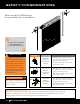
M250/L250 Roll -Up Door installation guide
Safety Considerations Please watch the DVD that has been provided prior to installation. DO NOT CuT BANDS or wrapping until instructed. W A R NING A rolling door is a large heavy object that moves with the help of springs under extreme tension and electric motors. Moving objects and springs under tension and electric motors can cause serious injuries or death. For your safety and the safety of others, follow these instructions.
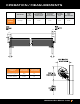
operation / measurements operation back of guide outside of bracket dual tension end outside of bracket axle support outside of tension end each end non-tension 2 1/2” 4 1/2” 4 1/2” 5 1/4” 2 1/2” M250 L250 Push-up 5 1/4” 4 1/2” 4 1/2” 3 3/4” 3 3/4” 2 1/2” 2 1/2” Opening Height Vertical Headroom Horizontal Headroom Less than or equal to 8’ 16.5” 17” Greater than 8’ 17.25” 19” www.muellerinc.
Step 1: WALL OPENING DO NOT CuT BANDS or wrapping until instructed. A C heck wall opening width and height and verify these measurements against size of door to be installed. B Verify that jambs are plumb. C Check floor and header for level. D Check for adequate side clearance at jambs and clearance above and at sides of header. See Clearance charts for minimum requirements. E Verify that the guide mounting surface on the jamb is flush.
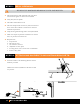
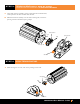
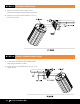
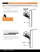
Step 3: TENSION END Right Side of Door (looking from the inside out) is Recommended A Using dual tensioner assembly’s spring roll pin located in knurled wheel, rotate upward in the direction that clears the axle. B Slide dual tensioner assembly over axle and tensioning hub, with arrow pointing toward wall. Release spring roll pin. Dual Tensioner Axle Wall Spring Roll Pin Tensioning Hub Set Screw Step 4: Non-tension end A Slide axle support over axle, with arrow pointing toward wall.
Step 5: tensioner end A Loosely attach dual tensioner assembly to door mounting bracket flange using the hardware provided. B Tighten the red, square headed, 3/8 inch set screw on the tensioner bracket. Step 6: non-tensioner end A Loosely attach axle support to door mounting bracket flange using the hardware provided. B Tighten the red, square headed, 3/8 inch set screw on the support bracket.
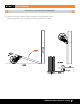
Step 7: lift door DO NOT CuT BANDS or wrapping. A After the axle support and dual tensioner are attached to mounting bracket, raise the assembly up against the door jambs and attach with the self-drill screw provided. www.muellerinc.
Step 8: ATTACHING GUIDES AND MOUNTING BRACKETS TO STEEL JAMB A Mounting brackets and guides must be attached using fasteners provided. B The opening edge of guides should be inset a very small amount (about 1/8 inch) from the door jamb opening on each side to minimize the potential of hitting the guides when entering through the door opening. Both guides must be plumb and level with each other.
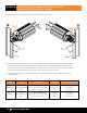
Step 9: ADJUSTING THE DOOR POSITION A Adjust the door height position using the slots on the mounting bracket. B Position door on mounting brackets with dual tensioner and tension axle support resting safely on top of mounting bracket flange. C Door should be positioned as close as possible to the door header and still be able to rotate the door so that the bottom bar will clear the door header.
Step 10: setting spring initial tension DO NOT CuT BANDS or wrapping until instructed. A Rotate door two revolutions, rotating the top of the door towards the opening. NOTE: If your building design does not allow for door rotation, lower the door curtain into the guides and follow the instructions in Step13 to set door tension.
D Install the Slide Lock with hardware provided. Optional on L250. Standard on M250. E Slide head stop from outside to inside of each mounting bracket. F Secure each head stop in the mounting brackets with the hardware provided. www.muellerinc.
Step 11: Make sure the top of guide is bent A If this is not bent; bend over headstop with Vise grips or an adjustable wrench. Step 12: check door operation A Once both head stops are securely installed and the top of the guide is bent over the headstop bar, unlock slide locks on the bottom bar and check door operation by lowering and raising the door.
Step 13: a djust spring tension door must be in fully open position to adjust spring. A Open door fully with the bottom bar resting against the head stops. B At dual tensioner end, place ½ inch ratchet into tensioning hub and hold the ratchet firmly. Have someone else loosen the square red headed 3/8 inch set screws on the dual tensioner and mounting bracket. Loss of spring tension will cause door curtain to drop rapidly. C To increase spring tension, pull down on ratchet 1/4 turn.
D T o decrease spring tension, momentarily pull down on ratchet and then lift the spring roll pin on the dual tensioner’s knurled wheel. Gently let up on the ratchet, allowing the axle to rotate ¼ turn to reduce the tension. While holding the new tension, release the dual tensioner’s spring roll pin. The dual tensioner will now grip the axle and help hold the new tension setting.
Step 16: add plugs A Insert the plugs provided as shown. The plugs must be inserted from the inside of the guide. If installed from the outside, the curtain will hang on the guide plugs. www.muellerinc.
M250/L250 Installation guide Call 877-2-mueller This toll-free number connects you to the branch nearest you. We have more than 20 locations across the southwest. click www.muellerinc.com Our website offers photos and details on all of our metal products. come by Our branches are staffed with experts who are always happy to answer any questions you have.