TM JULIAN WALKABOUT Use r s Manual 1
TABLE OF CONTENTS Preface 3 Design Goals 3 Precautions 3 Program Recommendations P 4 Components 4-5 Assembly 6-8 Adjustment Overview 9 Fitting Instructions 10-15 Measure the Child 10 Sit Bar, Hip & Upper Trunk Supports 10-11 Upper Body Pitch 11 Column Height 12 Spring Tension 13 Swivel Caster Lock 14 Adjustable Length Base 14 Headrest 14 Options 2 15-17 Hand Holds & Arm Troughs 15 Clear Tray Assembly 16 Double Sit Bar 17 Abduction Skirt 17 Operating Precautions 18
PREFACE This booklet provides the information required for the set up and use of the Julian WalkaboutTM. The benefits of using this system can be profound, not only in terms of gait development, but also in terms of increasing the child s independence, self confidence and social interaction. DESIGN GOALS The WalkaboutTM is designed to give a child the potential for hands-free, self-initiated movement while providing lateral support and assisted lift.
PROGRAM RECOMMENDATIONS Initially, many children use the WalkaboutTM as a stationary stander to develop standing tolerance and to develop hip and knee extension. Remember that spasticity has nothing to do with strength. A child with weak hip flexors may utilize their adductors to assist (this is not a good thing!) This situation can become more severe if the child has limited dorsiflexion. Try activities such as kicking or marching. Arrange obstacle courses to develop motor planning skills.
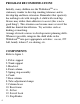
4 3 5 6 7 2 1 9 8 10 12 Figure 1 11 13 5
ASSEMBLY Tools Required: 3/16 allen wrench (included in pouch) 5/32 allen wrench (included in pouch) 1/4 allen wrench (included in pouch) Tape measure Adjustment Levers: Refer to figure 2. The adjustment levers can be ratcheted so the handle can rotate without affecting the tightness of the screw. 1. Pull out on black knob. Rotate the handle so it is not obstructed. 2. Release the black knob, and let Figure 2 the handle slide back and lock with the screw. 3.
Assembly Instructions: Column Adjustment Tube: Refer to figure 4 1. Place the base assembly on the floor. 2. Loosen the four allen screws on the tube adjustment clamps (1). 3. Slide the column adjustment tube (2) through the tube clamps. 4. Tighten all four allen screws on the tube clamps. Anti-Tipper: Refer to figure 5 1. Remove the ball lock pin (1) from the column adjustment tube. 2. Adjust the anti-tipper wheels so they are 1 to 2 from the ground 3. Reinsert the ball lock pin.
Column: Refer to figure 7 1. Loosen the T-nut (1) and remove the ball lock pin (2). 2. Slide the rear column into the column adjustment tube. 3. Replace the ball lock pin and tighten the T-nut to lock the column assembly in place. (Keep reading for further instructions on fine tuning.
ADJUSTMENT OVERVIEW Proper adjustment of the WalkaboutTM will significantly improve the child s success. The therapist is encouraged to try various adjustment combinations. If the child demonstrates primarily reflexive movements and postures, adjustments should be made to increase the amount of assistance that the stander provides. As the child s skill improves, adjustments should be made to decrease the amount of assistance.
FITTING INSTRUCTIONS Figure 8 Measure the Child: 1. Trunk width: ___ 2. Hip width: ___ 3. Inseam to 1 below his/her axilla: ___ 10 1 Sit Bar, Pelvic & Trunk 3 4 2 Supports: Refer to figure 8. 1. Loosen the two allen screws (1) on the back of the trunk bars. Adjust the width of the trunk bars to accommodate the child s 5 chest (use measurement #1 above). Make sure the bars are symmetrical on both sides. 2.
support assembly as close to the sit bar as possible without preventing hip flexion. If this support is too high or too low, it will not provide the stability required for the child to step forward. Tighten both screws. 7. Trunk pad height: Repeat step #4, but with the allen screws above and below the trunk pad (7). Pitch: Refer to figure 9 & 10.
Column Height: Refer to figure 11. After setting the pitch and the sit bar-to-trunk support distance, set the column height. 3 2 1. Measure the inseam: 1 Determine the child s inseam height: ____ a) If the child requires support at the upper trunk to stand, measure from the floor to 2 Figure 11 inches above the inseam. b) If the child requires only hip support to stand, measure from the floor to the inseam. 2.
Spring Tension: Refer to figures 12. The sit bar, pelvic support, and trunk support assist in lifting the child into standing. The amount of lift is controlled by the degree of spring tension. 1. Spring rate adjustment: The spring rate is the amount of force required to compress the spring a given amount. By sliding the black tubular spring stop (1) down, the spring becomes stiffer. To adjust, depress the silver slide lock button (2) and hold it in to release the spring stop. 2.
Adjustable Length Base: 1 Refer to figure 13 & 14. To extend the base of the WalkaboutTM simply pull up on the Figure 13 ring (13.1) and slide out the extension tube to the desired length. Both sides should be set to the same length. Caution: Adjust Figure 14 the length to suit the conditions of use. Extend the legs for play or for outdoor use. The WalkaboutTM may become unstable if the legs are too short for the conditions of use.
OPTIONS Handholds with arm troughs: Refer to Figure 17 & 18 1. Mounting: Hand holds 1 with arm troughs are mounted off the back of the sit bar (3). It is easiest 3 to mount with the sitbar 2 removed from the Figure 17 column. 2. Width: The width is adjusted by removing the ball lock pins (1) on the cross bar and sliding the tubes inwards or outwards. 3. Height: The height can be adjusted by loosening the clamps (2) and moving the hand hold posts up or down. Tighten the clamp again when adjusted to fit. 4.
Clear Tray Assembly: Refer to figure 19 Mounting: The tray mounting arms attach to the back of the sitbar, just like the hand holds. Please refer to the previous page for instructions. 1 Figure 19 Adjustments: 1. Width & Height: Refer to the Handholds instructions on the previous page. 2. Depth: Pull the ring on the spring clamps (1), located underneath the tray. Slide the tray along the tray bar to the desired depth. Release the ring and ensure the tray locks into place. 3.
Double Sit Bar: Refer to figure 20 1. Remove the current seat. 2. Slide the sit bar onto the front column. Secure at the desired height with the adjustment lever. Figure 20 Abduction Skirt: Refer to figure 21 1. Remove the current seat. 2. Slide the sit bar onto the front column. Secure at the desired height with the adjustment lever.
OPERATING PRECAUTIONS 1. Do not exceed the load limit shown on the name plate and in this manual. 2. The rear anti-tipper wheels need to be at least 1/2 (2.5cm) off the floor. If they are contacting the floor, the user cannot turn the device. 3. Adjust the height of the seat prior to putting the user in the device. 4. Adjust the spring tension after loading. 5. If the rear column tilts forward spontaneously you need to adjust the angle and TIGHTEN the clamp screws. 6.
TECHNICAL DATA Specifications: Physical Unit Weight: Weight Limit: Seat Height: Tilt Range: Width: Length: Turn Radius: Frame Color: Upholstery Color: WA Julian 26.5 lbs (12 kg) 55 lbs (25 kg) 7.5-24.5 (16.5-54cm) 75°-90° 22.5 (49.
839 Albion Ave P.O. Box 70 Burley, ID 83318 Phone: (208) 878-3840 (800) 543-4769 Fax: (208) 878-3841 info@mulhollandinc.com www.mulhollandinc.