ProStar MPPT TM Solar Charging System Controller Installation, Operation and Maintenance Manual For the most recent manual revisions, see the e-version at: www.morningstarcorp.com www.morningstarcorp.
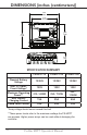
DIMENSIONS [inches (centimeters)] 7.88 (20.0 ) 6.69 (17.0 ) 4.92 (13.0) 6.69 (17.0) 2.78 ( 7.0 ) SPECIFICATION SUMMARY PS-MPPT-15 PS-MPPT-25 PS-MPPT-40 Nominal Battery Voltage 12/24V 12/24V 12/24V Max. PV OpenCircuit Voltage* 120V 120V 120V Maximum Operating Power** 210 / 420W 350 / 700W 550 / 1100W Max.
TABLE OF CONTENTS 1.0 Important Safety Instructions............................. 1 2.0 General Information..... .................................... ..10 2.1 2.2 2.3 2.4 2.5 Overview................................................................10 Regulatory Information........................................11 Versions and Ratings................................................13 Features.................................................................14 Optional Accessories..............................
.7.4 Using the Meter Display to Program Charging Set-points, Load Control, Communications, and Advanced Settings....................................................55 4.7.5 Lighting Control / Programming Overview...............55 4.7.6 Lighting Programming Using Meter Display.............56 4.8 Inspection and Maintenance..................................... 57 5.0 Troubleshooting...........................................59 5.1 5.2 LED Fault Indications.................................................. .
IMPORTANT SAFETY INSTRUCTIONS 1.0 1.0 SAVE THESE INSTRUCTIONS. This manual contains important safety, installation, operating and mantenance instructions for the ProStar MPPT solar controller. The following symbols are used throughout this manual to indicate potentially dangerous conditions or mark important safety instructions: WARNING: Indicates a potentially dangerous condition. Use extreme caution when performing this task.
Safety Information • Read all of the instructions and cautions in the manual before beginning installation. • There are no user serviceable parts inside the ProStar MPPT. Do not disassemble or attempt to repair the controller. WARNING: Risk Of Electrical Shock. NO POWER OR ACCESSORY TERMINALS ARE ELECTRICALLY ISOLATED FROM DC INPUT, AND MAY BE ENERGIZED WITH HAZARDOUS SOLAR VOLTAGE. UNDER CERTAIN FAULT CONDITIONS, BATTERY COULD BECOME OVERCHARGED. TEST BETWEEN ALL TERMINALS AND GROUND BEFORE TOUCHING.
• Déconnectez toutes les sources d’alimentation du contrôleur avant d’installer ou de régler le ProStar MPPT. • Le TriStar MPPT ne contient aucun fusible ou interrupteur. Ne tentez pas de réparer. • Installez des fusibles/coupe-circuits externes selon le besoin. Installation Safety Precautions WARNING: This unit is not provided with a GFDI device. This charge controller must be used with an external GFDI device as required by the Article 690 of the National Electrical Code for the installation location.
Ground Symbol • This charge controller is to be connected to DC circuits only. These DC connections are identified by the symbol below: Direct Current Symbol The ProStar MPPT controller must be installed by a qualified technician in accordance with the electrical regulations of the country of installation. A means of disconnecting all power supply poles must be provided. These disconnects must be incorporated in the fixed wiring.
1.0 • Montez le ProStar MPPT à l’intérieur. Empêchez l’exposition aux éléments et la pénétration d’eau dans le contrôleur. • Installez le MPPT ProStar dans un endroit qui empêche le contact occasionnel. Le dissipateur de chaleur ProStar MPPT peut devenir très chaud pendant le fonctionnement. • Utilisez des outils isolés pour travailler avec les batteries. • Évitez le port de bijoux pendant l’installation. • Le groupe de batteries doit être constitué de batteries du même type, fabricant et âge.
Le régulateur MPPT ProStar doit être installé par un technicien qualifié conformément aux règlements du pays d'installation électriques. Un moyen de déconnexion de tous les poteaux d'alimentation doit être fourni. Ceux-ci se déconnecte doit être intégrée dans le câblage fixe. Une mise à la terre permanent et fiable s'impose avec raccordement à la borne ProStar MPPT.
CAUTION: Do not open or mutilate batteries. Released electrolyte is harmful to skin, and may be toxic. PRUDENCE: Ne pas ouvrir ou mutiler les piles. L'électrolyte est nocif pour la peau et peut être toxique. • Servicing of batteries should be performed, or supervised, by personnel knowledgeable about batteries, and the proper safety precautions. • Be very careful when working with large lead-acid batteries. Wear eye protection and have fresh water available in case there is contact with the battery acid.
• Never smoke in the battery area. • If battery acid comes into contact with the skin, wash with soap and water. If the acid contacts the eye, flood with fresh water and get medical attention. • Be sure the battery electrolyte level is correct before starting charging. Do not attempt to charge a frozen battery. • Recycle the battery when it is replaced. • Entretien des batteries devrait être effectué ou supervisé, par un personnel bien informé sur les piles et les précautions de sécurité appropriées.
• En cas de contact de l’électrolyte avec la peau, lavez avec du savon et de l’eau. En cas de contact de l’électrolyte avec les yeux, rincez abondamment avec de l’eau fraîche et consultez un médecin. • Assurez-vous que le niveau d’électrolyte de la batterie est correct avant de commencer la charge. Ne tentez pas de charger une batterie gelée. • Recyclez la batterie quand elle est remplacée. ProStar MPPT Operator’s Manual 9 1.
2.0 GENERAL INFORMATION 2.1 Overview Thank you for choosing the ProStar MPPT charge controller with TrakStarTM MPPT Technology. The ProStar MPPT is an advanced maximum power point tracking solar battery charger. The controller features a smart tracking algorithm that finds and maintains operation at the power source's peak power point, maximizing energy harvest. The ProStar MPPT battery charging process has been optimized for long battery life and improved system performance.
2.2 Regulatory Information NOTE: This section contains important information for safety and regulatory requirements. (2) this device must accept any interference received, including interference that may cause undesired operation. Changes or modifications not expressly approved by Morningstar for compliance could void the user’s authority to operate the equipment. NOTE: This equipment has been tested and found to comply with the limits for a Class B digital device, pursuant to Part 15 of the FCC rules.
• Connect the equipment into an outlet on a circuit different from that to which the receiver is connected. • Consult the dealer, or an experienced radio/TV technician for help. This Class B digital apparatus complies with Canadian ICES-003. Cet appareil numerique de la classe B est conforme a la norme NMB-003 du Canada.
2.3 Versions and Ratings 2.
2.4 Features The features of the ProStar MPPT are shown in Figure 2-1 below. An explanation of each feature is provided. 8 1 2 9 3 10 4 11 12 13 5 6 14 7 15 16 Figure 2-1.
1 - Charging Status / Error LED Shows charging current and error condition statuses. 2 - Heatsink Aluminum heatsink (underneath) to dissipate controller heat (the ProStar MPPT is 100% passively cooled for reliability) 2.
2.5 Optional Accessories The following accessories are available for purchase separately from your authorized Morningstar dealer: Remote Temperature Sensor (Model: RTS) The RTS measures battery temperature for accurate temperature compensation and is recommended when the ambient battery temperature differs from the ambient controller temperature by more than 5º C. The standard cable length is 33 ft (10m). NOTE: The use of a Remote Temperature Sensor is strongly recommended.
• vent fan control • DIN rail compatible or surface mount 2.0 Ground-fault Protection Device (GFPD-150V) The GFPD-150V detects power source ground faults and interrupts current as required by the U.S. National Electrical Code. Wire Box for ProStar MPPT A modular wiring box that can be added to any version of ProStar MPPT controller. The box acts as a junction (using knock-outs) to run controller wiring to external conduit, if desired. The wire box cannot be used with rigid conduit.
3.0 INSTALLATION INSTRUCTIONS 3.1 General Installation Notes • Read through the entire installation section first before beginning installation. • Be very careful when working with batteries. Wear eye protection. Have fresh water available to wash and clean any contact with battery acid. • Use insulated tools and avoid placing metal objects near the batteries. WARNING: Equipment Damage or Risk of Explosion Never install the ProStar MPPT in an enclosure with vented/flooded batteries.
• The ProStar MPPT is designed to regulate ONLY solar (photovoltaic) power. Connection to any other type of power source e.g. wind turbine or generator may void the warranty. However, other power sources can be connected directly to the battery. • With the standard terminal cover, the maximum wire size is #6 AWG / 16 mm2 (solid/multi-strand) or #8 AWG / 10 mm2 (fine strand). When using the Wire Box accessory, the maximum wire size is #2 AWG.
• Stranded wires to be connected to the ProStar MPPT terminals should be prepared first with e.g. clamped copper heads, etc. to avoid the possibility of one conductor free out of the connection screw, and possible contact with the metal enclosure. WARNING: Solar and battery fuses or DC breakers are required in the system. These protection devices are external to the ProStar MPPT controller, and must be a maximum of 30 amps for the PS-MPPT-25/M and 50 amps for the PS-MPPT-40/M.
3.2 Configuration The DIP switch block shown in Figure 3.1 below is used to set the operating parameters for the ProStar MPPT. 3.0 Figure 3.1.
NOTE: Before connecting the battery, measure the open-circuit voltage. It must be over 10 volts to start the controller. If the system voltage Settings Switches are set to Auto-detect, battery voltage over 15.5V will be detected as a 24V nominal battery, and the unit will charge accordingly. The 12/24V auto selection is only done at start-up, and the detected system voltage will never change during operation.
Switch 7: Battery Equalization Mode Switch 7 Manual Equalization OFF Auto Equalization ON Switch 8: Meterbus / MODBUS Settings Switch 8 Meterbus OFF MODBUS ON ProStar MPPT Operator’s Manual 3.
3.3 Mounting Inspect the controller for shipping damage. Mount the ProStar MPPT to a vertical surface (4-#8 stainless steel self-tapping screws are included). Tighten the mounting screws, using care not to crack the plastic case. Do not install directly over an easily combustible surface since the heat sink may get hot under certain operating conditions. NOTE: The heat sink must be in a vertical position (fins up and down).
3.4 Wiring 3.0 SS+- 3 S- S+ 7 L- L+ 5 B+ 2 B- 4 6 To battery (+) and (-) terminals for voltage sensing 1 To properly sized array To load (+) and (-) terminals To battery (+) and (-) terminals To battery for temperature sensing Figure 3-3. Wiring the PS-MPPT REFER TO FIGURE 3.3 WHEN USING THE WIRING INSTRUCTIONS BELOW. NOTE: THE PS-MPPT IS UL 1741 COMPLIANT WHEN USED WITH THE OPTIONAL WIRE BOX. THE WIRE BOX CANNOT BE USED WITH RIGID CONDUIT.
STEP 1: Check Controller Limitations Verify that the highest temperature compensated solar array open-circuit voltage (Voc), and load current do not exceed the ratings of the ProStar MPPT version being installed. Multiple controllers can be installed in parallel on the same battery bank to achieve greater total charging current. In this type of system, each ProStar MPPT must have its own solar array.
the true battery voltage would only be 14.1 volts, if there is a 0.3 volt drop between the controller and battery. Note that the battery sense wires will not power the controller, and the sense wires will not compensate for losses in the power wires between the controller and the battery. The battery sense wires are used to improve the accuracy of the battery charging.
STEP 3: Remote Temperature Sensor WARNING: Risk of Fire. If no Remote Temperature Sensor (RTS) is connected, use the ProStar MPPT within 3m (10 ft) of the batteries. Internal Temperature Compensation will be used if the RTS is not connected. Use of the RTS is strongly recommended. AVERTISSEMENT: Risque d'incendie. Si non Capteur de température distant (RTS) est connecté, utilisez le MPPT ProStar moins de 3m (10 pi) de les batteries.
CAUTION: The ProStar MPPT will use the local temperature sensor for compensation if the RTS is not used. PRUDENCE: Le TriStar MPPT ne compense pas la température des paramètres de charges si le RTS n’est pas utilisé. REMARQUE: Le câble de RTS peut être raccourci si la totalité de la longueur n’est pas nécessaire. Assurez-vous de réinstaller la bobine en ferrite sur l’extrémité du RTS si une longueur de câble est enlevée. Cette bobine assure la conformité avec les normes d’émissions électromagnétiques.
Figure 3-4. Ground Symbol WARNING: Risk of Fire DO NOT bond system electrical negative to earth ground at the controller. Per NEC requirements, system negative must be bonded to earth ground through a GFPD at only one point. AVERTISSEMENT : Risque d’incendie NE LIEZ PAS le côté négatif du système à la mise à la terre au niveau du contrôleur. Selon les exigences du CNE, le côté négatif du système doit être mis à la terre par un GFPD à un seul point.
3.0 STEP 5: Load Connections Turn the loads off, and connect the load wires to the load terminals. DO NOT CLOSE BREAKER AT THIS TIME. BATTERY (+) BATTERY (-) 30 or 50 Amp Breaker - depending on model 6 in (150 mm) MAX.
STEP 6: Battery Connections Be sure that DIP switches 2 and 3 are set for 12 or 24V, as described in Section 3.2 NOTE: Before connecting the battery, measure the open-circuit voltage. It must be over 10 volts to start the controller. If the system voltage Settings Switches are set to Auto-detect, battery voltage over 15.5V will be detected as a 24V nominal battery, and the unit will charge accordingly. The 12/24V auto selection is only done at start-up.
AVERTISSEMENT: Risque de décharge électrique Le réseau PV solaire peut produire des tensions de circuit ouvert supérieures à 120 Vdc à la lumière du soleil. Vérifiez que le coupe-circuit ou l’interrupteur d’entrée solaire a été ouvert (déconnexion) avant d’installer les câbles du système. With the solar disconnect open, connect the solar (PV) array wires to the PS-MPPT solar terminals. Use caution, since the solar array will produce current whenever in sunlight.
• there is an overload condition (LEDs blinking R/Y - G) • the load is not connected, not working, or turned off After all connections have been completed, observe the LEDs to make sure the controller is operating normally for system conditions. If the optional digital meter is used, observe that the display is scrolling with proper voltage and current values. Also, a self- test can be performed with digital meter units.
4.0 OPERATION 4.1 TrakStar MPPT Technology The ProStar MPPT utilizes Morningstar’s TrakStar Maximum Power Point Tracking technology to extract maximum power from the solar module(s). The tracking algorithm is fully automatic and does not require user adjustment. Trakstar technology will track the array maximum power point voltage (Vmp) as it varies with weather conditions, ensuring that maximum power is harvested from the array through the course of the day.
High Voltage Strings and Grid-tie Modules Another benefit of TrakStar MPPT technology is the ability to charge 12 or 24 volt batteries with solar arrays of higher nominal voltages. A 12 volt battery bank can be charged with a 12, 24, 36 or 48V nominal off-grid solar array. Certain grid-tie solar modules may also be used as long as the solar array open circuit voltage (Voc) rating will not exceed the ProStar MPPT 120V maximum input voltage rating at worstcase (lowest) module temperature.
4.2 Battery Charging Information 4-Stage Charging VOLTAGE The ProStar MPPT has a 4-stage battery charging algorithm for rapid, efficient, and safe battery charging. Figure 4-2 shows the sequence of stages. EQUALIZE BULK CHARGE 4.0 NIGHT ABSORPTION FLOAT NIGHT TIME Figure 4.2. ProStar MPPT Charging Algorithm Bulk Charge Stage During Bulk charging, the battery is not at 100% state of charge and battery voltage has not yet charged to the Absorption voltage set-point.
The battery must remain in the Absorption charging stage for a cumulative 120 - 150 minutes, depending on battery type, before transition to the Float stage will occur. However, Absorption time will be extended by 30 minutes if the battery discharges below 12.50 volts (12V system) the previous night. The Absorption set-point is temperature compensated if the RTS is connected.
Equalization Stage WARNING: Risk of Explosion Equalizing vented batteries produces explosive gases. The battery bank must be properly ventilated. ! CAUTION: Equipment Damage Excessive overcharging and gasing too vigorously can damage the battery plates and cause shedding of active material from the plates. An equalization that is too high or for too long can be damaging. Review the requirements for the particular battery being used in your system.
battery voltage above the standard absorption voltage so that the electrolyte gases. The green SOC LED will blink rapidly two (2) times per second during equalization charging. The duration of the equalize charge is determined by the selected battery type. See table 4-1 in this section for more details. The Equalization Time is defined as time spent at the equalization set-point.
Equalize a Sealed Battery? The Battery Charging Settings table (see table 4-1 in this section) shows two sealed battery settings with an Equalization cycles. These are minimal “boost” cycles to level individual cells. This is not an equalization, and will not vent gas from sealed batteries that require up to 14.4V charging (12V battery). Many VRLA batteries, including AGM and gel, have charging requirements up to 14.4V (12V battery).
the “boost” cycle for sealed cells can be disabled by setting the equalize setting switch to manual, if required. Battery Charge Settings Preset ProStar MPPT battery charging options are shown in tables 4-1 and 4-2 below. All voltage settings listed are for nominal 12 Volt batteries. Multiply the voltage settings by two (2) for 24 Volt batteries. NOTE: These settings are general guidelines for use at the operator’s discretion.
The ProStar MPPT provides seven (7) standard battery charging settings that are selected with the settings switches (see Table 4.1 above). These standard charging settings are suitable for lead-acid batteries ranging from sealed (gel, AGM, maintenance-free) to Flooded and L-16 cells. In addition, an eighth charging setting provides for custom set-points using MSViewTM PC software. Table 4-1 above summarizes the major parameters of the standard charging settings.
Float Time-out Bulk Absorption Float SubFloat Bulk Absorption Float V 60 mins. below Float 1:00 2:00 3:00 4:00 5:00 6:00 time (hrs) Figure 4-4. Float Exit Time-out Charging Profile After entering Float stage, the controller will only exit Float if the battery voltage remains below Float voltage for 60 cumulative minutes. In figure 4-4, a system load turns on at 4:00 hrs when the controller is in Float stage, runs for one hour, and turns off at 5:00 hrs.
Float Cancel Voltage 4.0 Figure 4.5. Float Cancellation Charging Profile If the battery bank discharges below 12.30 volts (24.60 volts @ 24 V) the previous night, Float charging stage will be cancelled for the next charge cycle. Figure 4-5 above, illustrates this concept. At 0:00 hrs (dawn), battery voltage is below the Float Cancel threshold voltage. The diagram shows where Float stage would have occurred if Float was not canceled.
Equalize Time-out Figure 4.6. Equalize Time-out Charging Profile The charging profile in figure 4-6 above, shows an Equalize Timeout event. The timeout timer begins as soon as battery voltage exceeds the Absorption voltage setpoint. If there is insufficient charging current or system loads are too large, the battery voltage may not reach the Equalize setpoint. Equalize Time-out is a safety feature that prevents high battery voltage for extended periods of time which may damage the battery.
4.3 Load Control Information The primary purpose of the load control function is to disconnect system loads when the battery has discharged to a low state of charge and reconnect system loads when the battery is sufficiently recharged. System loads may be lights, pumps, motors, DC appliances, and other electronic devices. The total current draw of all loads must not exceed the ProStar MPPT 25 or 30 amp maximum load rating.
The amount of time between a green SOC indication and load disconnect will depend on many factors including: • rate of discharge (amount of load draw) • capacity of the battery • health of the battery • LVD set-point If the battery discharges to the LVD set-point the load will disconnect and a solid red Battery Status LED indication will be displayed.
4.4 LED Indications KEY: G = green Y = yellow R = red G - Y - R = flashing sequencially G/Y = flashing together G / Y - R = G and Y flashing together, alternating with R flash 4.4.1. Power-up Normal power-up: Status LED flashes G, then SOC LEDS flash G - Y - R, then SOC LEDs indicate battery charge status with a single battery status LED. 4.0 Failed bootload: Status LED flashes G, then SOC LEDS flash G - Y and stop on solid Y. 4.4.
NOTES: 1) R flashing is generally a user addressable fault / error 2) R charging status LED ON with heartbeat blink OFF every 5 secs is a critical fault that generally requires service. See, "Solid Charging Status LED with Self-test (R-Y-G) SOC Faults", in Section 5.1. 4.4.3 State-of-Charge LEDs Battery SOC LED Indications are shown in Table 4-5 below: Condition Indication Absorption Float Equalize SOC > 13.5V 13.5V > SOC > 13.0V 13.0V > SOC > 12.5V SOC < 12.
Lighting Control Mode (DIP 1 ON) • A quick press and release will clear any faults or reminders that are present. A second quick press will then conduct a lighting test. If no faults or reminders are present, the initial press will conduct a lighting test. A lighting test is used to verify correct wiring in the load circuit and/or verify the lighting components are operational.
airflow and that the heatsink temperature is approaching unsafe limits. If the controller frequently reports this alarm condition, corrective action must be taken to provide better air flow or to relocate the controller to a cooler spot. High Input Voltage Current Limit The ProStar MPPT will limit the solar input current as the solar array Voc approaches the maximum input voltge rating. The array Voc should never exceed the 120 volt maximum input voltage - see the array voltage de-rating graph in Appendix.
4.7 Custom Settings 4.7.1 Programming with the Meter Display The ProStar MPPT is available in metered and non-metered versions. The metered model allows: • Custom programming, including lighting programs, directly from the unit. • Extensive settings adjustment and information as shown partially in Figure 4-7 below: Display Screens and Programming Models: PS-MPPT-25M PS- MPPT- 40M 4.
4.7.2 Programming in MSView Beyond the preset DIP switch options, the Prostar MPPT's charging profile and all other settings are customizable using MSView PC software available at: www.morningstarcorp.com WARNING: Risk Of Electrical Shock. Hazardous voltage is present at the Meterbus communications port. Use 150V rated, 4 or 6 conductor UL listed telephone cable. AVERTISSEMENT: Risque de choc électrique. Tension dangereuse est présente dans le port de communication de transfert.
4.7.3 Meter Display Operation 4.7.3.1 Directional Key Use and Operation / Navigating the Meter Map The ProStar MPPT's meter map consists of two main axes: The horizontal top level daily monitoring screens, and the vertical Main Menu stacked screens. The four lighted triangular directional control keys allow movement to reach any desired point on the meter map. A lit key indicates a valid direction in the map. The current location is indicated on the display with a column heading, and a bold descriptor. 4.
With DIP switch 1 ON (up), a dusk-dawn lighting program is enabled, if lighting timing hasn't been programmed in MSView or using the meter; with DIP 1, 4, 5, 6 ON, and the unit programmed, custom timing will be in effect. With DIP 1 OFF (down), all lighting control functions are disabled. Using either MSView or the meter display, four channels are available for setting timers that can work separately, or in combination. See Section 4.6.6 - Lighting Programming Using Meter Display - for more details. 4.7.
4.8 Inspection and Maintenance Table 4-6 below lists the recommended maintenance schedule to keep your ProStar MPPT performing optimally. WARNING: RISK OF ELECTRICAL SHOCK. NO POWER OR ACCESSORY TERMINALS ARE ELECTRICALLY ISOLATED FROM DC INPUT, AND MAY BE ENERGIZED WITH HAZARDOUS SOLAR VOLTAGE. UNDER CERTAIN FAULT CONDITIONS, BATTERY COULD BECOME OVERCHARGED. TEST BETWEEN ALL TERMINALS AND GROUND BEFORE TOUCHING.
Schedule Maintenance Items 2 weeks after installation Re-tighten power terminal connections to specified torque values. 3 months after installation Re-tighten power terminal connections to specified torque values. Monthly or After Each Equalization Inspect the battery bank. Look for cracked or bulging cases, and corroded terminals. For wet cell (flooded type) batteries, make sure the water level is correct.
5.0 TROUBLESHOOTING WARNING: RISK OF ELECTRICAL SHOCK. NO POWER OR ACCESSORY TERMINALS ARE ELECTRICALLY ISOLATED FROM DC INPUT, AND MAY BE ENERGIZED WITH HAZARDOUS SOLAR VOLTAGE. UNDER CERTAIN FAULT CONDITIONS, BATTERY COULD BECOME OVERCHARGED. TEST BETWEEN ALL TERMINALS AND GROUND BEFORE TOUCHING. AVERTISSEMENT: RISQUE DE CHOC ÉLECTRIQUE. NON ALIMENTATION OU AUX BORNES D'ACCESSOIRES SONT ISOLÉS ÉLECTRIQUEMENT DE L'ENTRÉE DE C.C ET DOIT ÊTRE ALIMENTÉS À UNE TENSION DANGEREUSE SOLAIRE.
disconnected. A small overload could take a few minutes to disconnect. The ProStar MPPT will attempt to reconnect the load two (2) times. Each attempt is approximately 10 seconds apart. If the overload remains after two (2) attempts, the load will remain disconnected until power is removed and re-applied. Solar Short Circuit Charging Status LED: OFF. Solar input power wires are short-circuited. Charging automatically resumes when the short is cleared.
can be used to determine if the RTS is working properly. Battery Sense Cables Issue Error status LED: Flashing red. Battery status LEDs: R/Y - G/Y sequencing. If a fault in the battery sense connection (such as a short-circuit, open circuit or loose terminal) occurs after the battery sense has been working, the LEDs will indicate a failure. To resume operation without battery sense cables, disconnect all power to the ProStar MPPT and then re-connect.
Battery Over-Current Error status LED: Flashing red. Battery status LEDs: R/Y-G sequencing. While rare, if battery charging current exceeds approximately 130% of the controller’s output current rating, this fault can occur. The fault is generally related to fast, large battery voltage transients (connecting a very heavy or capacitive load like an inverter) that are faster than the controller can regulate and it shuts off to protect the circuitry. The controller will automatically re-start in 10 seconds.
SOLID CHARGING STATUS LED with SELF-TEST (R-Y-G) SOC FAULTS Verify that nothing has been mis-wired. If not, the error is likely critical. Contact an authorized Morningstar dealer for support.
5.2 Battery Charging and Performance Issues Problem: No LED indications, controller does not appear to be powered Solution: With a multi-meter, check the voltage at the battery terminals on the ProStar MPPT. Battery voltage must be 10 vdc or greater. If the voltage on the battery terminals of the controller is between 10 and 35 vdc, and no LEDs are lit, contact your authorized Morningstar dealer for service. If no voltage is measured, check wiring connections, fuses, and breakers.
6.0 WARRANTY & POLICIES LIMITED WARRANTY Morningstar Solar Controllers and Inverters All of Morningstar’s products, with the exception of the SureSine™ 300 inverter and SHS™ controller, are warrantied to be free from defects in material and workmanship for a period of FIVE (5) years from the date of shipment to the original end user.
MORNINGSTAR TECHNICAL SUPPORT POLICIES Morningstar’s Technical Support Group is dedicated to providing unparalleled customer support. MS Support Scope: 1. Determining correct or failed functionality of a Morningstar product or system of Morningstar devices. It is expected that owners/operators will use manuals (including trouble shooting sections) before requesting technical support. 2. Providing product warranty replacements in accordance with the terms of Morningstar’s warranty policy. 3.
MORNINGSTAR TECHNICAL SUPPORT POLICIES (Cont.) ♦ Please visit the Tech Support section at www.morningstarcorp.com for any documentation or specification needs before requesting support. The site also offers an array sizing tool (String Selector), product comparison tool (Product Comparator) and articles on solar charging technologies and other design considerations. ♦ Although emergencies do arise when a phone call is necessary, e-mail is the best way to contact us, and will result in the quickest response.
WARRANTY CLAIM PROCEDURE 1. Before proceeding, please refer to product manual, including Trouble Shooting section. 2. Contacting your authorized Morningstar distributor or dealer from whom you purchased the unit is the first step in the warranty process. Local dealers can often address warranty issues quickly. 3. If supplier is unable to address the issue, please contact Morningstar by e-mail (support@morningstarcorp.
7.0 TECHNICAL SPECIFICATIONS PS-MPPT-15 PS-MPPT-25 PS-MPPT-40 PS-MPPT-15M PS-MPPT-25M PS-MPPT-40M Electrical: Nominal Battery Voltage 12 volts or 24 volts (all) Battery Voltage Range 10-35 volts (all) Voltage Accuracy 0.1% +/- 50mV (all) Max. Battery Current 15 amps 25 amps 40 amps Max.
Battery Charging Set-points (@ 25°C): [multiply voltages by (2) for 24 volt systems] DIP Switch Settings 4-5-6 Absorp. Stage (volts) Float Stage (volts) off-off-off 1 - Sealed* 14.00 13.70 off-off-on 2 - Sealed* 14.15 13.70 14.40 off-on-off 3 - Sealed* 14.30 13.70 14.65 off-on-on 14.40 13.70 on-off-off 5 - Flooded 14.60 on-off-on 6 - Flooded 14.70 on-on-off 7 - L-16 on-on-on 8 - Custom Battery Type 4- AGM/Flooded Equalize Stage (volts) Absorp.
Data & Communications: Communication Port Comm.
100.00% 99.00% 98.00% 97.00% 96.00% 95.00% 94.00% 93.00% 92.00% 91.00% 90.00% 89.00% 88.00% 87.00% 86.00% 85.00% 84.00% 83.00% 82.00% 81.00% 80.00% 79.00% 78.00% 77.00% 76.00% 75.00% 74.00% 73.00% 72.00% 71.00% 70.
Efficiency (%) 100.00% 99.00% 98.00% 97.00% 96.00% 95.00% 94.00% 93.00% 92.00% 91.00% 90.00% 89.00% 88.00% 87.00% 86.00% 85.00% 84.00% 83.00% 82.00% 81.00% 80.00% 79.00% 78.00% 77.00% 76.00% 75.00% 74.00% 73.00% 72.00% 71.00% 70.
APPENDIX B - De-rating Graphs O V E R - V O L T A G E 40 R A N G E ! Battery Current (Amps) Battery Current vs. Array Voltage (Vmp) 0 80 85 90 95 100 105 110 115 120 Array Voltage (Volts) Battery Current vs.
APPENDIX C - Wire Sizing Charts 2% Voltage Drop Charts for 75°C Stranded Copper Wire 1-Way Wire Distance (feet), 12 Volt System Wire Size (AWG) 40A 35A 30A 25A 20A 15A 10A 5A 2/0 * 33.6 38.4 44.8 53.8 67.2 89.6 134.4 268.9 1/0 * 26.6 30.4 35.5 42.6 53.3 71.0 106.6 213.1 2 16.8 19.1 22.3 26.8 33.5 44.7 67.0 134.0 4 10.6 12.1 14.1 16.9 21.1 28.1 42.2 84.4 6 6.6 7.6 8.8 10.6 13.2 17.7 26.5 53.0 8 4.2 4.8 5.6 6.7 8.4 11.1 16.7 33.4 10 2.6 3.0 3.
2% Voltage Drop Charts for 75°C Solid Copper Wire 1-Way Wire Distance (feet), 12 Volt System Wire Size (AWG) 40A 35A 30A 25A 20A 15A 10A 5A 2/0 * 41.7 47.7 55.6 66.7 83.4 111.2 166.8 333.6 1/0 * 33.1 37.8 44.1 52.9 66.1 88.2 132.3 264.6 2 20.8 23.8 27.7 33.3 41.6 55.4 83.2 166.3 4 13.1 14.9 17.4 20.9 26.2 34.9 52.3 104.6 6 8.2 9.4 11.0 13.2 16.5 21.9 32.9 65.8 8 5.2 5.9 6.9 8.3 10.3 13.8 20.7 41.4 10 3.3 3.7 4.3 5.2 6.5 8.7 13.0 26.
*Wires sizes larger than 2 AWG (35 mm2) must be terminated at a splicer block located outside of the ProStar MPPT wiring box. Use 2 AWG (35 mm2) or smaller wire to connect to the ProStar MPPT to the splicer block. Notes: • The specified wire length is for a pair of conductors from the solar or battery source to the controller (1-way distance) • For 24 volt systems, multiply the 1-way length in the table by 2.
2% Voltage Drop Charts for 90°C Stranded Copper Wire 1-Way Wire Distance (feet), 12 Volt System Wire Size (AWG) 40A 35A 30A 25A 20A 15A 10A 5A 2/0 * 33.6 38.4 44.8 53.8 67.2 89.6 134.4 268.9 1/0 * 26.6 30.4 35.5 42.6 53.3 71.0 106.6 213.1 2 16.8 19.1 22.3 26.8 33.5 44.7 67.0 134.0 4 10.6 12.1 14.1 16.9 21.1 28.1 42.2 84.4 6 6.6 7.6 8.8 10.6 13.2 17.7 26.5 53.0 8 4.2 4.8 5.6 6.7 8.4 11.1 16.7 33.4 10 2.6 3.0 3.5 4.2 5.2 7.0 10.5 21.
2% Voltage Drop Charts for 90°C Solid Copper Wire 1-Way Wire Distance (feet), 12 Volt System Wire Size (AWG) 40A 35A 30A 25A 20A 15A 10A 5A 2/0 * 41.7 47.7 55.6 66.7 83.4 111.2 166.8 333.6 1/0 * 33.1 37.8 44.1 52.9 66.1 88.2 132.3 264.6 2 20.8 23.8 27.7 33.3 41.6 55.4 83.2 166.3 4 13.1 14.9 17.4 20.9 26.2 34.9 52.3 104.6 6 8.2 9.4 11.0 13.2 16.5 21.9 32.9 65.8 8 5.2 5.9 6.9 8.3 10.3 13.8 20.7 41.4 10 3.3 3.7 4.3 5.2 6.5 8.7 13.0 26.
*Wires sizes larger than 2 AWG (35 mm2) must be terminated at a splicer block located outside of the ProStar MPPT wiring box. Use 2 AWG (35 mm2) or smaller wire to connect to the ProStar MPPT to the splicer block. Notes: • The specified wire length is for a pair of conductors from the solar or battery source to the controller (1-way distance) • For 24 volt systems, multiply the 1-way length in the table by 2.
8.0 CERTIFICATIONS ALL COMPONENTS REACH COMPLIANT Registration, Evaluation and Authorization of Chemicals • Complies with UL 1741, UL 62109 and CSA-C22.2 No. 107.